Speed control DC motor and rotary encoder with PID Control
อีก 1 โครงงาน สำหรับการควบคุมความเร็วให้กับมอเตอร์ไฟฟ้ากระแสตรง (DC Motor) และใช้ PID Control เป็นอัลกอลิทึมในการควบคุมความเร็ว ด้วยการตรวจจับสัญญาณ Rotary encoder ซึ่งติดมาพร้อมกับตัวมอเตอร์แล้ว ซึ่งจะช่วยลดเวลาในการเลือกใช้และติดตั้ง Rotary encoder ได้ โดยมอเตอร์ที่เลือกใช้จะเป็นรุ่น CHR-GM25-370 ใช้แรงดันที่ 12Vdc เท่านั้น
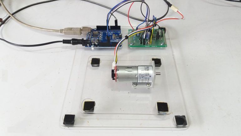
ในรูปที่ 1 จะเป็นลักษณะการประกอบอุปกรณ์ต่างๆ ให้เป็นลักษณะบอร์ดทดลองเพื่อให้ง่ายต่อการเรียนรู้และทดลองต่างๆ ซึ่งจะประกอบด้วย 3 ส่วนใหญ่ คือ ส่วนของบอร์ดประมวลผลจะใช้ Arduino UNO ส่วนที่ 2 จะเป็นส่วนของบอร์ดขับมอเตอร์, วงจรเรกูเลตและส่งสัญญาณ Encoder ให้กับบอร์ดประมวลผล และส่วนของตัวดีซีมอเตอร์
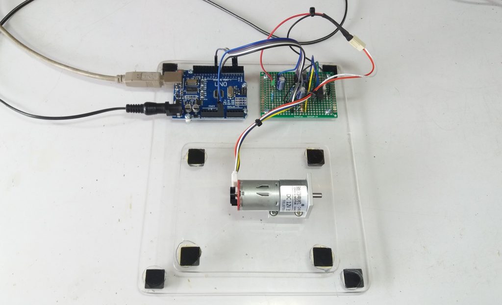
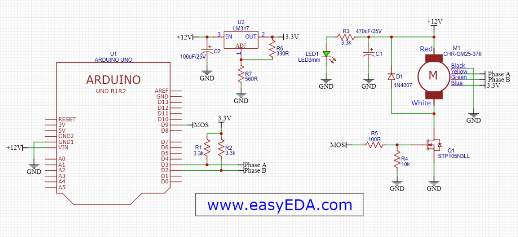
ในรูปที่ 2 จะเป็นการต่อวงจรร่วมกันระหว่างบอร์ดประมวลผลและบอร์ดขับมอเตอร์ โดยในส่วนของบอร์ดขับมอเตอร์จะรับไฟเลี้ยงทั้งหมดจากแหล่งจ่ายอะแดปเตอร์ เพื่อให้ง่ายต่อการทดลองและมีกระแสพอสำหรับใช้ในวงจรนี้ทั้งหมด
ในโครงงานนี้สำหรับการสลับทิศทางการหมุนของตัวมอเตอร์นั้น ให้เราสลับสายไฟที่ต่อระหว่างบอร์ดขับมอเตอร์เป็นสายไฟ สีแดงและสีดำ กับคอนเน็กเตอร์ตัวมอเตอร์ สีแดงและสีขาว ก็สามารถใช้งานได้ ซึ่งเราจะสามารถเห็นลักษณะของสัญญาณ Encoder ที่เกิดขึ้นจากการสลับทิศทางนี้
*Code Program Arduino UNO
#include <PID_v1.h>
#define PIN_INPUT 0
#define PIN_OUTPUT 9

int time_H;
int time_L;
int Frequency;
int encoder0PinA = 2;
int encoder0PinB = 3;
int encoder0Pos = 0;
int encoder0PinALast = LOW;
int n = LOW;
float t_period;
int sampleRate = 10;
double Setpoint, Input, Output;
double Kp=1, Ki=5, Kd=0.001;
PID myPID(&Input, &Output, &Setpoint, Kp, Ki, Kd, DIRECT);

void setup()
{
Serial.begin(9600);
pinMode (encoder0PinA,INPUT);
pinMode (encoder0PinB,INPUT);
pinMode (PIN_OUTPUT, OUTPUT);
Setpoint = 1000;
myPID.SetSampleTime(sampleRate);
myPID.SetMode(AUTOMATIC);
Serial.print(" ");
Serial.print("Test SP = ");
Serial.print(Setpoint);
Serial.print(" Hz");
delay(1000);
analogWrite(PIN_OUTPUT,40); // Start up DC Motor
delay(100);
}

void loop()
{
n = digitalRead(encoder0PinA);
if ((encoder0PinALast == LOW) && (n == HIGH)) { // Test For Signal A and B Direction
if (digitalRead(encoder0PinB) == LOW) {
// encoder0Pos--; // Recommend not to use
Serial.print (" CW, "); // Mark Direction CW
} else {
// encoder0Pos++; // Recommend not to use
Serial.print (" CCW, "); // Mark Direction CCW
}

time_H = pulseIn(encoder0PinA,HIGH);
time_L = pulseIn(encoder0PinA,LOW);
t_period = time_H+time_L;
t_period = t_period/1000;
Frequency = 1000/t_period;
if(Frequency>3000){ // Set error Variable for t_period more
Frequency = 0;
}
Input = Frequency;
Serial.print("PV = "); // Recommend not to use
Serial.print(Input); // Recommend not to use
myPID.Compute();
analogWrite(PIN_OUTPUT, Output);
Serial.print(" PWM = "); // Recommend not to use
Serial.println(Output); // Recommend not to use
}
encoder0PinALast = n;
}
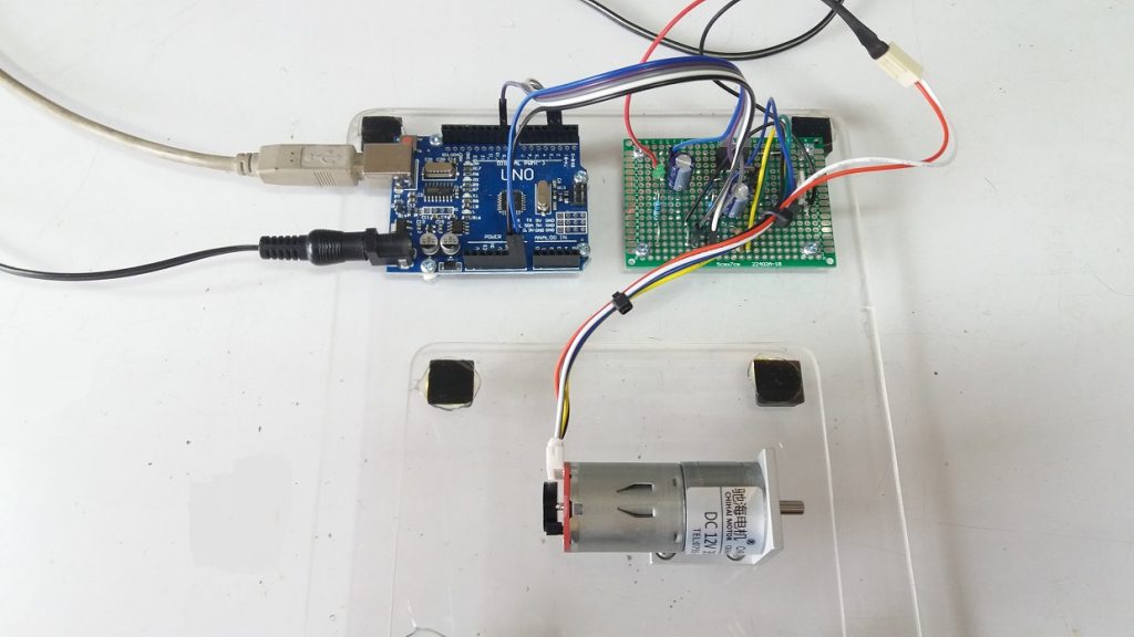
สำหรับโครงงานนี้เป็นโครงงานเล็กๆ ที่พอจะเป็นไอเดียให้ท่านสามารถนำไปต่อยอดในการนำไปใช้งานต่างๆได้บ้างนะครับ และในรูปข้างบนที่ 4 จะแสดงวงจรที่ใช้ในการทดลองโครงงานของส่วนต่างๆ ซึ่งเราสามารถปรับแต่งวงจรนี้ให้ใช้งานได้ตามความเหมาะสม
*Information
- https://p.globalsources.com/IMAGES/PDT/SPEC/301/K1123392301.pdf
- https://www.puntoflotante.net/MOTOR-CD-MOTORREDUCTOR-ENCODER.htm
- http://www.learningaboutelectronics.com/Articles/Rotary-encoder-circuit.php
- https://diyodemag.com/education/what_the_tech_rotary_encoders
- https://en.wikipedia.org/wiki/PID_controller
- https://th.wikipedia.org/wiki/%E0%B8%A3%E0%B8%B0%E0%B8%9A%E0%B8%9A%E0%B8%84%E0%B8%A7%E0%B8%9A%E0%B8%84%E0%B8%B8%E0%B8%A1%E0%B8%9E%E0%B8%B5%E0%B9%84%E0%B8%AD%E0%B8%94%E0%B8%B5