Sensorless BLDC Motor Control Based on Arduino UNO
โครงงานนี้เป็นการควบคุมความเร็วของมอเตอร์แบบไม่ใช้แปรงถ่านและไม่มีตัวเซนเซอร์ตำแหน่ง (Sensorless BLDC Motor) ด้วยการใช้บอร์ด Arduino UNO ในการประมวลผลและใช้มอเตอร์ในกลุ่มบังคับวิทยุมาทดลอง ซึ่งบางครั้งเรียกกันว่า Brushless DC Motor ส่วนหนึ่งเราจะใช้บอร์ดขับมอเตอร์ที่สร้างขึ้นเอง และวงจรที่เราต่อขึ้นมาเพิ่มเติม ซึ่งจะทำหน้าที่ตรวจจับตำแหน่งของโรเตอร์ (Rotor) ที่เกิดจากสัญญาณแรงดันย้อนกลับ (Back EMF) เพื่อควบคุมการหมุนนั้นเอง
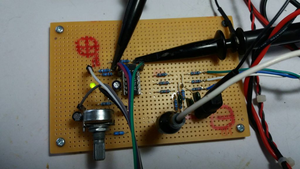
ในรูปข้างบนที่ 2 จะเป็นบอร์ดตรวจจับตำแหน่งของโรเตอร์ ที่ใช้วงจรในลักษณะแบ่งแรงดัน (Voltage Divider) และวงจรกรองความถี่ต่ำผ่าน (Low pass filter) ในการปรับค่าแรงดันย้อนกลับให้สมบูรณ์ จากนั้นเมื่อได้สัญญาณที่ต้องการแล้วก็จะนำมาเข้าวงจรเปรียบเทียบอีกครั้งด้วยไอซี LM339 เพื่อให้ลักษณะของสัญญาณมีความถูกต้องมากยิ่งขึ้น และสามารถใช้ในการประมวลผลกับไมโครคอนโทรลเลอร์ได้อย่างถูกต้อง
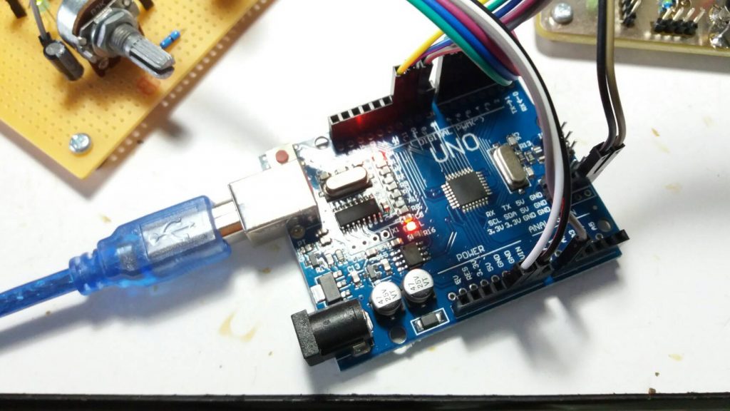
รูปข้างบนที่ 3 จะเป็นลักษณะของบอร์ดควบคุมการทำงานทั้งหมด ซึ่งจะเป็นบอร์ด Arduino UNO โดยตัวบอร์ดจะรับสัญญาณควบคุมความเร็วจากตัวต้านทานปรับค่า (POT) เข้ามาที่ขา A0 และสัญญาณควบคุมอีกส่วนมาจากบอร์ดตรวจจับตำแหน่งของโรเตอร์เพื่อกำหนดการสร้างสัญญาณอินเวอร์เตอร์ในการขับให้กับสเตเตอร์ (Stator) นอกจากนี้บอร์ดควบคุม จะส่งสัญญาณอินเวอร์เตอร์ 6 ช่องให้กับบอร์ดขับกำลังให้กับตัวมอเตอร์อีกครั้ง ซึ่งจะมีลำดับการทำงานตามที่กำหนด
Program Arduino UNO Ref. https://simple-circuit.com/arduino-sensorless-brushless-motor-bldc/
/* Sensorless brushless DC motor control with Arduino UNO and IR2101 (Arduino DIY ESC).
- BLDC motor speed is controlled with a potentiometer connected to A0.
- This is a free software with NO WARRANTY.
- https://simple-circuit.com/
- https://simple-circuit.com/arduino-sensorless-brushless-motor-bldc/
*/
#define PWM_MAX_DUTY 250
#define PWM_MIN_DUTY 15 // 50
#define PWM_START_DUTY 50 // 100
byte bldc_step = 0, motor_speed, pin_state;
void setup()
{
DDRD |= 0xE0; // configure pins 5, 6 and 7 as outputs
PORTD = 0x00;
DDRB |= 0x0E; // configure pins 9, 10 and 11 as outputs
PORTB = 0x31;
// Timer1 module setting: set clock source to clkI/O / 1 (no prescaling)
TCCR1A = 0;
TCCR1B = 0x01;
// Timer2 module setting: set clock source to clkI/O / 1 (no prescaling)
TCCR2A = 0;
TCCR2B = 0x01;
// ADC module configuration
ADMUX = 0x60; // configure ADC module and select channel 0
ADCSRA = 0x84; // enable ADC module with 16 division factor (ADC clock = 1MHz)
PCICR = EIMSK = 0; // disable all external interrupts
pinMode(2, INPUT_PULLUP);
pinMode(3, INPUT_PULLUP);
pinMode(4, INPUT_PULLUP);
}
// pin change interrupt 2 (PCINT2) ISR
ISR (PCINT2_vect)
{
if( (PIND & PCMSK2) != pin_state )
return;
// BEMF debounce
for(byte i = 0; i < 20; i++)
{
if(bldc_step & 1){
if(PIND & PCMSK2) i -= 1;
}
else {
if(!(PIND & PCMSK2)) i -= 1;
}
}
bldc_move();
bldc_step++;
bldc_step %= 6;
}
// BLDC motor commutation function
void bldc_move()
{
switch(bldc_step)
{
case 0:
AH_BL();
BEMF_C_FALLING();
break;
case 1:
AH_CL();
BEMF_B_RISING();
break;
case 2:
BH_CL();
BEMF_A_FALLING();
break;
case 3:
BH_AL();
BEMF_C_RISING();
break;
case 4:
CH_AL();
BEMF_B_FALLING();
break;
case 5:
CH_BL();
BEMF_A_RISING();
}
}
void loop()
{
SET_PWM_DUTY(PWM_START_DUTY); // setup starting PWM with duty cycle = PWM_START_DUTY
int i = 5000;
// motor start
while(i > 100)
{
delayMicroseconds(i);
bldc_move();
bldc_step++;
bldc_step %= 6;
i = i – 20;
}
motor_speed = PWM_START_DUTY;
PCICR = 4; // enable pin change interrupt for pins PCINT23..16 (Arduino 0 to 7)
while(1)
{
ADCSRA |= 1 << ADSC; // start conversion
while(ADCSRA & 0x40); // wait for conversion complete
motor_speed = ADCH; // read ADC data (8 bits only)
if(motor_speed < PWM_MIN_DUTY)
motor_speed = PWM_MIN_DUTY;
SET_PWM_DUTY(motor_speed);
}
}
void BEMF_A_RISING()
{
PCMSK2 = 0x04; // enable Arduino pin 2 (PCINT18) interrupt, others are disabled
pin_state = 0x04;
}
void BEMF_A_FALLING()
{
PCMSK2 = 0x04; // enable Arduino pin 2 (PCINT18) interrupt, others are disabled
pin_state = 0;
}
void BEMF_B_RISING()
{
PCMSK2 = 0x08; // enable Arduino pin 3 (PCINT19) interrupt, others are disabled
pin_state = 0x08;
}
void BEMF_B_FALLING()
{
PCMSK2 = 0x08; // enable Arduino pin 3 (PCINT19) interrupt, others are disabled
pin_state = 0;
}
void BEMF_C_RISING()
{
PCMSK2 = 0x10; // enable Arduino pin 4 (PCINT20) interrupt, others are disabled
pin_state = 0x10;
}
void BEMF_C_FALLING()
{
PCMSK2 = 0x10; // enable Arduino pin 4 (PCINT20) interrupt, others are disabled
pin_state = 0;
}
void AH_BL()
{
PORTD &= ~0xA0;
PORTD |= 0x40;
TCCR1A = 0; // turn pin 11 (OC2A) PWM ON (pin 9 & pin 10 OFF)
TCCR2A = 0x81; //
}
void AH_CL()
{
PORTD &= ~0xC0;
PORTD |= 0x20;
TCCR1A = 0; // turn pin 11 (OC2A) PWM ON (pin 9 & pin 10 OFF)
TCCR2A = 0x81; //
}
void BH_CL()
{
PORTD &= ~0xC0;
PORTD |= 0x20;
TCCR2A = 0; // turn pin 10 (OC1B) PWM ON (pin 9 & pin 11 OFF)
TCCR1A = 0x21; //
}
void BH_AL()
{
PORTD &= ~0x60;
PORTD |= 0x80;
TCCR2A = 0; // turn pin 10 (OC1B) PWM ON (pin 9 & pin 11 OFF)
TCCR1A = 0x21; //
}
void CH_AL()
{
PORTD &= ~0x60;
PORTD |= 0x80;
TCCR2A = 0; // turn pin 9 (OC1A) PWM ON (pin 10 & pin 11 OFF)
TCCR1A = 0x81; //
}
void CH_BL()
{
PORTD &= ~0xA0;
PORTD |= 0x40;
TCCR2A = 0; // turn pin 9 (OC1A) PWM ON (pin 10 & pin 11 OFF)
TCCR1A = 0x81; //
}
void SET_PWM_DUTY(byte duty)
{
OCR1A = duty; // set pin 9 PWM duty cycle
OCR1B = duty; // set pin 10 PWM duty cycle
OCR2A = duty; // set pin 11 PWM duty cycle
}
ในส่วนข้างบนนี้จะเป็นตัวโปรแกรมที่ใช้งานการทดลองโครงงาน ซึ่งอ้างอิงมาจากเว็บไซต์ https://simple-circuit.com/arduino-sensorless-brushless-motor-bldc ซึ่งเราสามารถใช้ในการทดลองและปรับแต่งเพื่อให้สามารถใช้งานได้อย่างเหมาะสม
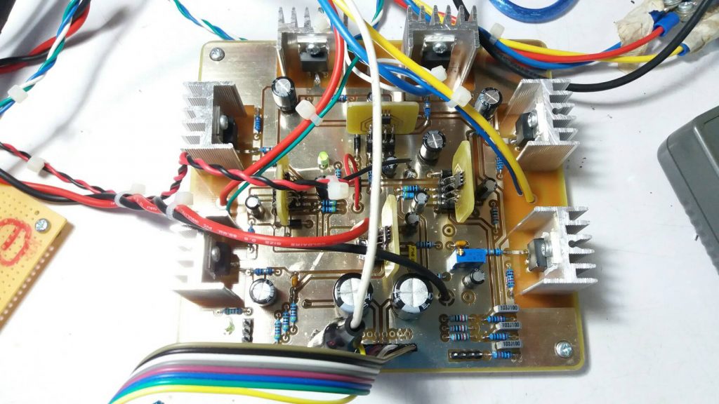
ในรูปข้างบนที่ 4 จะเป็นบอร์ดสำหรับขับ BLDC Motor ที่เราสามารถต่อไฟเลี้ยงและส่งสัญญาณควบคุม 6 ช่องเข้ามาได้ทันที โดยไฟเลี้ยงจะใช้ 2 ชุด คือไฟเลี้ยงสำหรับตัวมอเตอร์ตั้งแต่ 12V-35Vdc และสำหรับชุดขับที่ขาเกตไอซีที่ 12V-15V ซึ่งตัวบอร์ดสามารถตรวจจับกระแสที่ไหลผ่านมอเตอร์ได้ และสามารถต่อกับมอเตอร์ BLDC Motor แบบมีตัวตรวจจับตำแหน่งได้โดยตรงและเราจะได้สัญญาณที่จะใช้ในการประมวลผลทันที
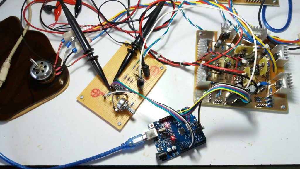
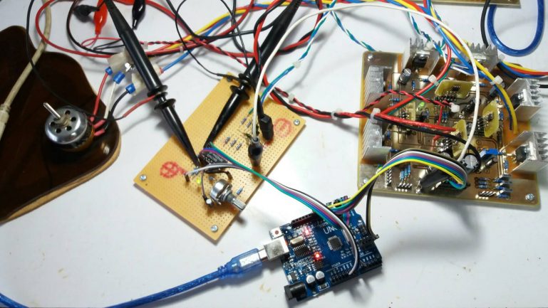
ในรูปสุดท้ายที่ 5 จะเป็นลักษณะของการต่ออุปกรณ์ต่างๆ ทั้งหมดเข้าด้วยกัน และลักษณะของการทดลองที่เกิดขึ้น โดยเราสามารถปรับความเร็วของตัวมอเตอร์ได้ด้วยตัวต้านทานปรับค่าที่เห็น และหวังว่าโครงงานนี้น่าจะเป็นพื้นฐานให้กับทุกท่านพัฒนาโครงงานของตัวเองในรูปแบบต่างๆ ที่ต้องการได้นะครับ.
Reference