Control Stepper motor 2CH and A4988 Module by ESP32 Devkit
โครงงานนี้จะเป็นการทดลองใช้ ESP32 Devkit สำหรับควบคุมการทำงานของสเต็ปเปอร์ มอเตอร์ (Stepper motor) อีกแบบหนึ่งครับ ซึ่งก่อนหน้านี้เคยนำเสนอเกี่ยวกับการควบคุมเซอร์โวมอเตอร์ (Servo motor) และกระแสตรง (DC Motor) ไปแล้วครับ ซึ่งโครงงานทั้ง 3 แบบนี้น่าจะเป็นแนวทางในการนำ NodeMCU ESP32 Devkit ไปใช้ในการควบคุมมอเตอร์ได้หลายแบบนะครับ
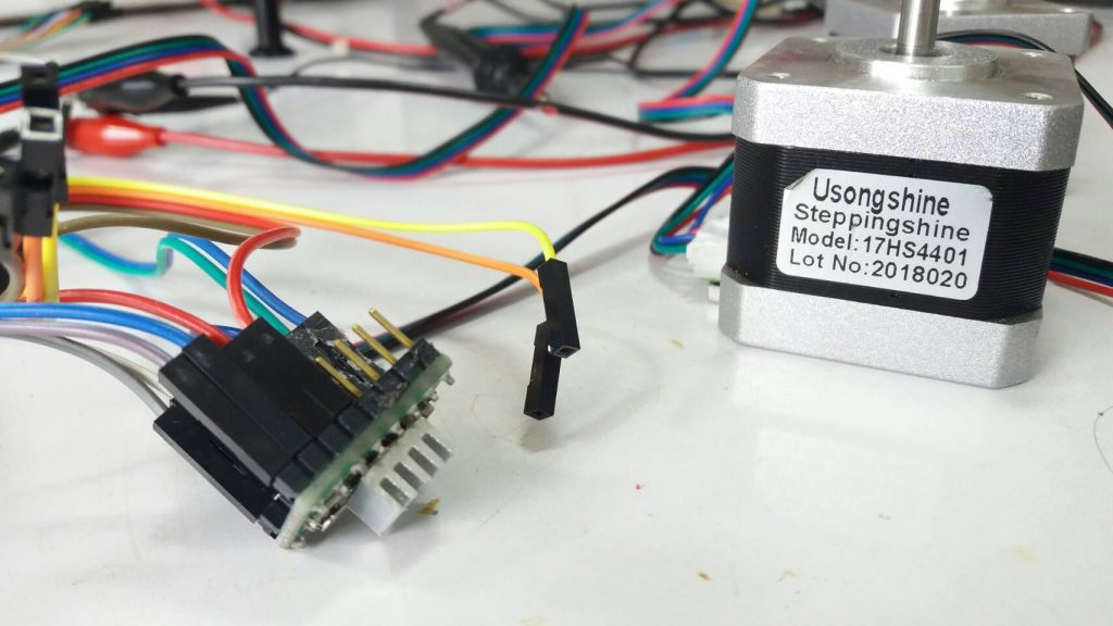
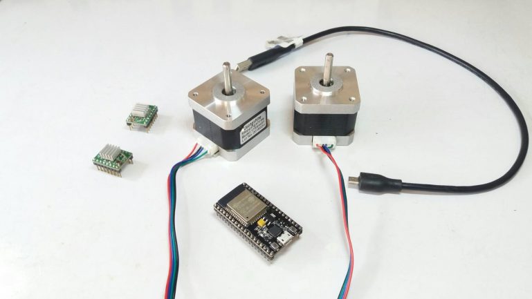
ในรูปที่ 1 แสดงอุปกรณ์สำหรับขับสเต็ปเปอร์มอเตอร์ด้วยโมดูล A4988 และตัวสเต็ปเปอร์มอเตอร์ รุ่น 17HS4401 ซึ่งทั้ง 2 ส่วนนี้สามารถเชื่อมต่อการใช้งานได้ง่ายและค่อนข้างสำเร็จแล้ว
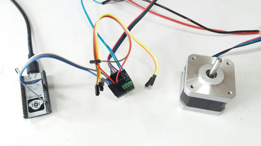
รูปที่ 2 จะมาเริ่มทดลองการทำงานด้วยการต่อโมดูล A4988 และตัวสเต็ปเปอร์มอเตอร์ เพื่อทดลองการทำงานเบื้องต้นก่อน 1 ตัว รวมทั้งทดสอบการทำงานของโปรแกรม เพื่อเป็นแนวทางสำหรับนำไปประยุกต์ใช้งานอีกครั้ง
โปรแกรมทดลองการทำงานที่ 1 (ใช้สเต็ปเปอร์มอเตอร์ 1 ตัว)
/* Example sketch to control a stepper motor
with A4988 stepper motor driver and Arduino without a library.
More info: https://miliohm.com/how-to-drive-a-stepper-motor-easily-using-a4988-and-arduino/
: https://www.makerguides.com/a4988-stepper-motor-driver-arduino-tutorial/
*/
// Define stepper motor connections and steps per revolution:
define dirPin 4
define stepPin 16
define stepsPerRevolution 300

void setup() {
// Declare pins as output:
pinMode(stepPin, OUTPUT);
pinMode(dirPin, OUTPUT);
}

void loop() {
// Set the spinning direction clockwise:
digitalWrite(dirPin, HIGH);
// Spin the stepper motor 1 revolution slowly:
for (int i = 0; i < stepsPerRevolution; i++) {
// These four lines result in 1 step:
digitalWrite(stepPin, HIGH);
delayMicroseconds(1000);
digitalWrite(stepPin, LOW);
delayMicroseconds(1000);
}
delay(1000);
// Set the spinning direction counterclockwise:
digitalWrite(dirPin, LOW);
// Spin the stepper motor 1 revolution quickly:
for (int i = 0; i < stepsPerRevolution; i++) {
// These four lines result in 1 step:
digitalWrite(stepPin, HIGH);
delayMicroseconds(1000);
digitalWrite(stepPin, LOW);
delayMicroseconds(1000);
}
delay(1000);
digitalWrite(dirPin, HIGH);
// Spin the stepper motor 5 revolutions fast:
for (int i = 0; i < 5 * stepsPerRevolution; i++) {
// These four lines result in 1 step:
digitalWrite(stepPin, HIGH);
delayMicroseconds(600);
digitalWrite(stepPin, LOW);
delayMicroseconds(600);
}
delay(1000);
// Set the spinning direction counterclockwise:
digitalWrite(dirPin, LOW);
//Spin the stepper motor 5 revolutions fast:
for (int i = 0; i < 5 * stepsPerRevolution; i++) {
// These four lines result in 1 step:
digitalWrite(stepPin, HIGH);
delayMicroseconds(600);
digitalWrite(stepPin, LOW);
delayMicroseconds(600);
}
delay(1000);
}
จากการทดลองเบื้องต้นกับตัวสเต็ปเปอร์มอเตอร์ 1 ตัวนั้น สามารถใช้งานได้โดยจะเป็นการปรับความเร็วในการหมุนเป็น 2 ระดับ คือ ต่ำและสูง และทดลองแรงบิดของตัวมอเตอร์ที่ความเร็ว 2 ระดับนี้ โดยผลที่ได้คือที่ความเร็วต่ำจะให้แรงบิดที่สูงกว่า เมื่อเทียบกับควาเร็วที่สูงขึ้น และในช่วงมอเตอร์สแตนบายจะเกิดการใช้งานกระแสในตัวมอเตอร์สูง แต่เมื่อมอเตอร์หมุนก็จะทำให้วงจรกินกระแสลดลงและที่ความเร็วสูงก็จะมีสัดส่วนของการกินกระแสลดลง
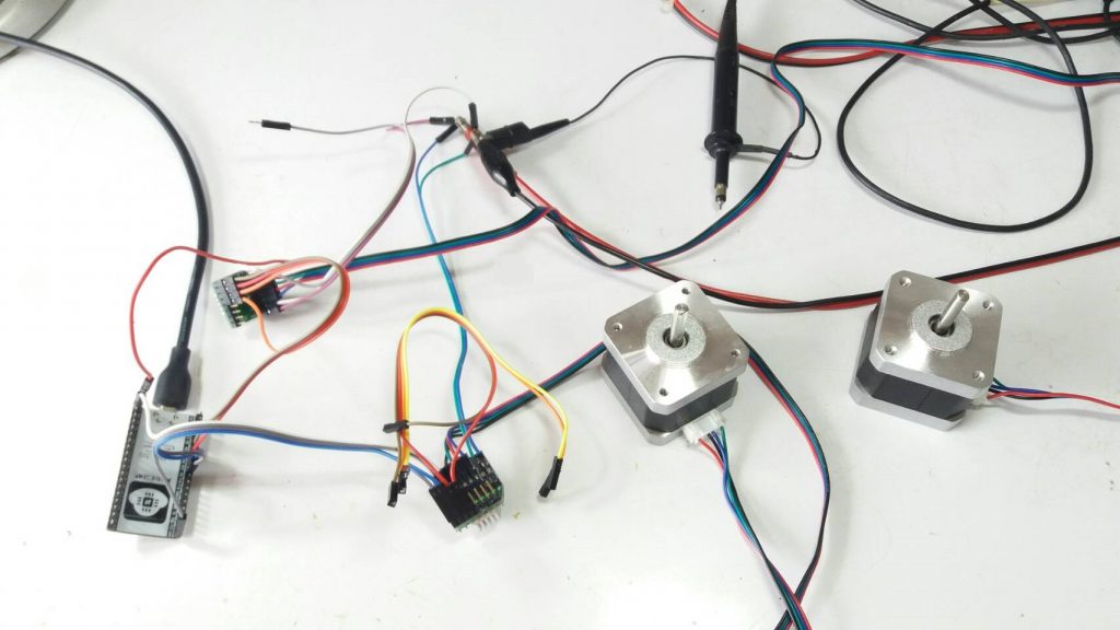
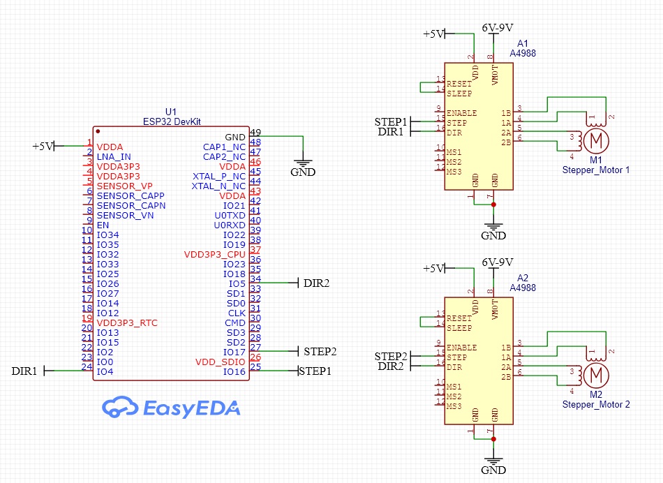
สำหรับในรูปที่ 3 จะเป็นการทดลองด้วยการใช้ตัวสเต็ปเปอร์มอเตอร์ 2 ตัว แบบทำงานแยกอิสระจากกัน ทั้งนี้เพื่อให้เราสามารถนำไปประยุกต์เป็นหุ่นยนต์ต่างๆ ควบคุมผ่านอินเตอร์เน็ต (IoT) ได้ง่ายยิ่งขึ้น ซึ่งท่านสามารถใช้โปรแกรมทดลองการทำงานที่ 2 นี้นำไปใช้งานได้ทันที
รูปนกเขามาเที่ยวตอนกำลังทดลองครับ ^_^. พอดีกำลังทดลองวงจรอยู่ก็บินเข้ามาแล้วก็หาทางออกจากห้องที่ทดลองไม่เจอ ครั้งนี้เป็นครั้งที่ 3 ครับ เล่นกันแป๊บนึงแล้วก็ปล่อยไปเหมือนเดิมครับ.
โปรแกรมทดลองการทำงานที่ 2 (ใช้สเต็ปเปอร์มอเตอร์ 2 ตัว)
/* Example sketch to control a stepper motor
with A4988 stepper motor driver and Arduino without a library.
More info: https://miliohm.com/how-to-drive-a-stepper-motor-easily-using-a4988-and-arduino/
: https://www.makerguides.com/a4988-stepper-motor-driver-arduino-tutorial/
*/
// Define stepper motor connections and steps per revolution:
#define dirPin1 4
#define stepPin1 16
#define dirPin2 5
#define stepPin2 17
#define stepsPerRevolution 300

void setup() {
// Declare pins as output:
pinMode(stepPin1, OUTPUT);
pinMode(dirPin1, OUTPUT);
pinMode(stepPin2, OUTPUT);
pinMode(dirPin2, OUTPUT);
}
void loop() {

// Set the spinning direction clockwise:
digitalWrite(dirPin1, HIGH);
digitalWrite(dirPin2, HIGH);
// Spin the stepper motor 1 revolution slowly:
for (int i = 0; i < stepsPerRevolution; i++) {
// These four lines result in 1 step:
digitalWrite(stepPin1, HIGH);
digitalWrite(stepPin2, HIGH);
delayMicroseconds(1000);
digitalWrite(stepPin1, LOW);
digitalWrite(stepPin2, LOW);
delayMicroseconds(1000);
}
delay(1000);
// Set the spinning direction counterclockwise:
digitalWrite(dirPin1, LOW);
digitalWrite(dirPin2, LOW);
// Spin the stepper motor 1 revolution quickly:
for (int i = 0; i < stepsPerRevolution; i++) {
// These four lines result in 1 step:
digitalWrite(stepPin1, HIGH);
digitalWrite(stepPin2, HIGH);
delayMicroseconds(1000);
digitalWrite(stepPin1, LOW);
digitalWrite(stepPin2, LOW);
delayMicroseconds(1000);
}
delay(1000);
digitalWrite(dirPin1, HIGH);
digitalWrite(dirPin2, HIGH);
// Spin the stepper motor 5 revolutions fast:
for (int i = 0; i < 5 * stepsPerRevolution; i++) {
// These four lines result in 1 step:
digitalWrite(stepPin1, HIGH);
digitalWrite(stepPin2, HIGH);
delayMicroseconds(600);
digitalWrite(stepPin1, LOW);
digitalWrite(stepPin2, LOW);
delayMicroseconds(600);
}
delay(1000);
// Set the spinning direction counterclockwise:
digitalWrite(dirPin1, LOW);
digitalWrite(dirPin2, LOW);
//Spin the stepper motor 5 revolutions fast:
for (int i = 0; i < 5 * stepsPerRevolution; i++) {
// These four lines result in 1 step:
digitalWrite(stepPin1, HIGH);
digitalWrite(stepPin2, HIGH);
delayMicroseconds(600);
digitalWrite(stepPin1, LOW);
digitalWrite(stepPin2, LOW);
delayMicroseconds(600);
}
delay(1000);
}
การต่อใช้งานอุปกรณ์ต่างๆ เข้าด้วยกันนั้น ดูได้จากรูปวงจรข้างล่างครับ โดยในส่วนของแหล่งจ่ายไฟเลี้ยง 5V เราสามารถใช้บนบอร์ด NodeMCU ESP32 ได้ทันทีทั้งนี้ในส่วนของไฟเลี้ยง 5V จะใช้พลังงานไม่มากนัก แต่ในส่วนของไฟเลี้ยงที่ 6V-9V จะต้องใช้ไฟเลี้ยงแยกอีกส่วนหนึ่ง โดยในส่วนนี้ไฟเลี้ยงจะต้องจ่ายกำลังให้กับสเต็ปเปอร์มอเตอร์โดยตรงและใช้พลังงานสูง
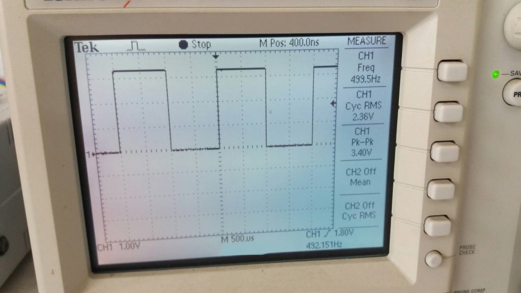
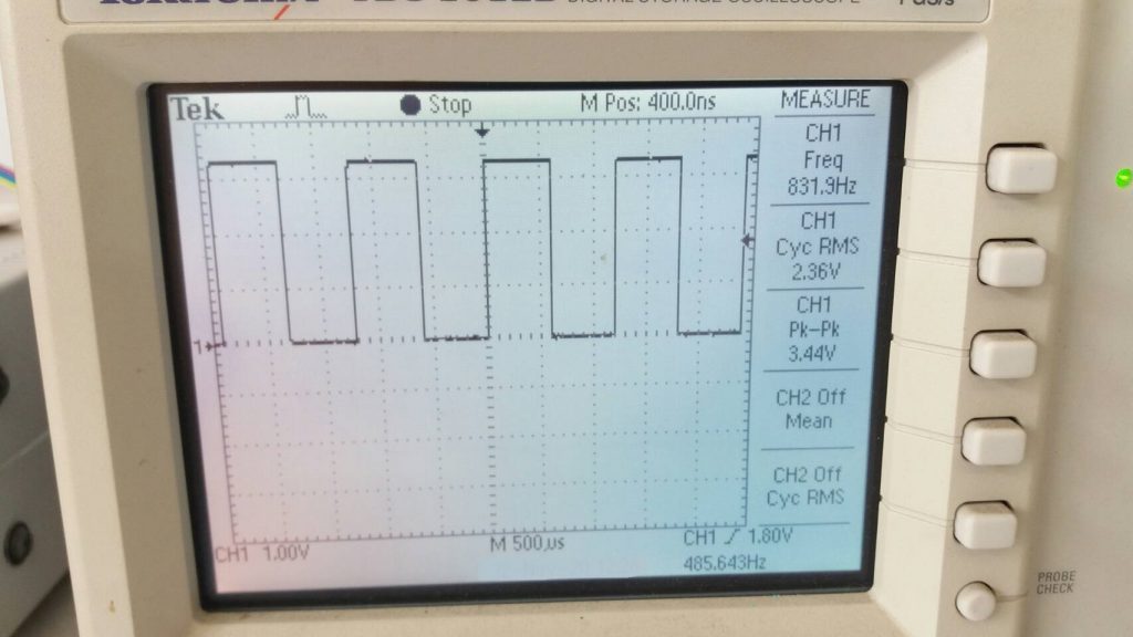
สำหรับในรูปที่ 4 และ 5 สัญญาณที่เกิดขึ้นนี้ทำให้เห็นการเปลี่ยนแปลงในเรื่องของความเร็วตัวมอเตอร์ที่แตกต่างกัน โดยสัญญาณจะถูกกำหนดค่าดิวตี้ไซเกิลไว้เท่ากับ 50% และขนาดของแอมปริจูดจะมีค่าประมาณ 3.3Vp-p ซึ่งเป็นระดับของไฟเลี้ยงให้กับชิป ESP32 นั้นเอง
สำหรับโครงงานนี้เป็นโครงงานเล็กๆ ที่จะเป็นไอเดียให้ท่านนำไปใช้งานในด้านต่างๆ อย่าง Internet of Things : IoT นะครับ ซึ่งก่อนหน้านี้ได้นำเสนอโครงงานที่นำเอา NodeMCU ESP32 Devkit มาใช้งานร่วมกับมอเตอร์แบบต่างๆ กันบ้างแล้ว และให้มีความหลากหลายของเนื้อหาเพิ่มขึ้นครับ.
Reference
- https://www.pololu.com/file/0J450/a4988_DMOS_microstepping_driver_with_translator.pdf
- https://miliohm.com/how-to-drive-a-stepper-motor-easily-using-a4988-and-arduino/
- https://www.makerguides.com/a4988-stepper-motor-driver-arduino-tutorial/
- https://lastminuteengineers.com/a4988-stepper-motor-driver-arduino-tutorial/