Analog comparator of ATMEGA328P with Library AnalogComp.h

การทดลองนี้เป็นการใช้งานออปแอมป์ภายในตัวชิฟไมโครคอนโทรลเลอร์ ATMEGA328P ด้วยบอร์ด Arduino UNO สำหรับเปรียบเทียบค่าแรงดันระหว่างตำแหน่งขา PD6 = AIN0 และ PD7 = AIN1 ซึ่งเราสามารถใช้งานออปแอมป์ภายในชิฟได้อีกรูปแบบหนึ่งนอกจากการใช้วิธีการอ่านค่าแรงดันด้วยขา ADC0-ADC5 ซึ่งมีรูปแบบการทำงานที่แตกต่างกัน โดยในการทดลองจะนำตัวอย่างโปรแกรมแบบใช้วิธีกำหนดค่ารีจิสเตอร์ Analog comparator โดยตรง และตัวอย่างโปรแกรมด้วยการใช้ไลบารี่ AnalogComp.h ทั่วไปเพื่อให้ใช้งานได้ง่ายยิ่งขึ้นและเป็นแนวทางสำหรับนำไปใช้งานต่างๆ ต่อไป
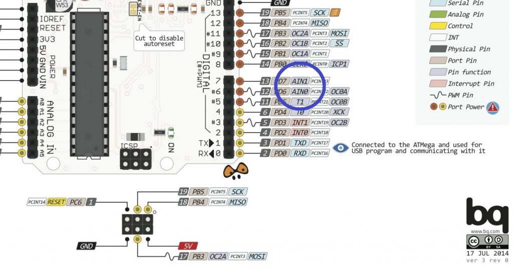
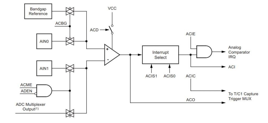
รูปที่ 1 แสดงตำแหน่งขาใช้งาน AIN0 และ AIN1 ของบอร์ด Arduino UNO ซึ่งจะตรงกับขา PD6 = AIN0 และ PD7 = AIN1 ตามลำดับ และในรูปที่ 2 จะเป็นบล็อกไดอะแกรมภายในของ Analog Comparator รวมทั้ง ฺBit ควบคุมการทำงานที่สำคัญในแต่ละตำแหน่งให้เข้าใจการทำงานได้ง่ายขึ้น
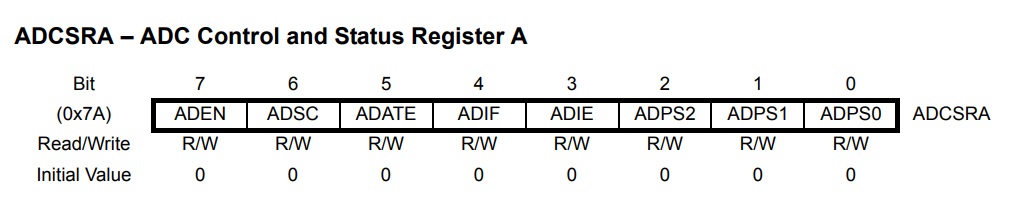
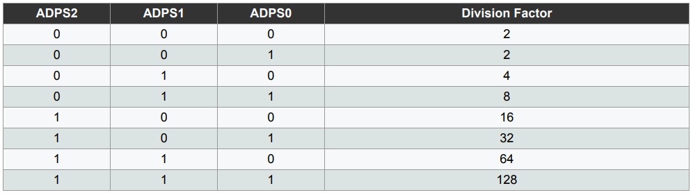
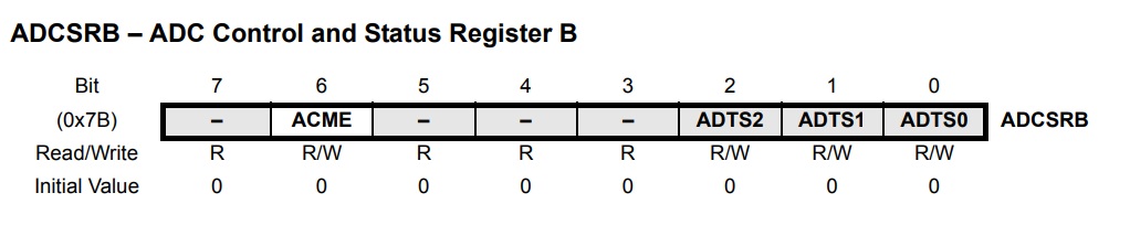
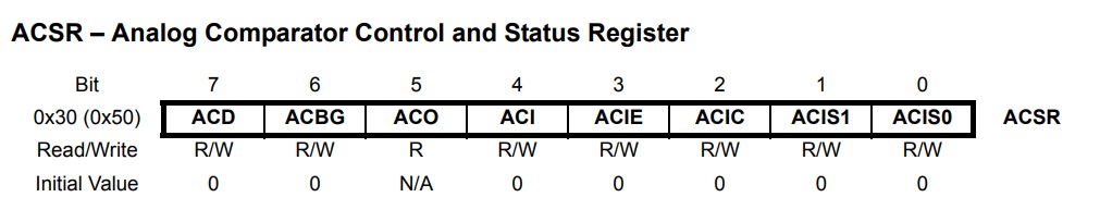
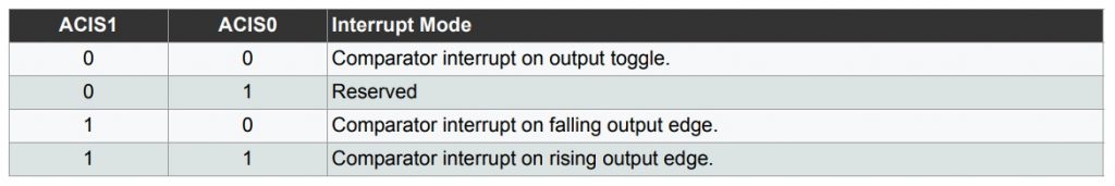
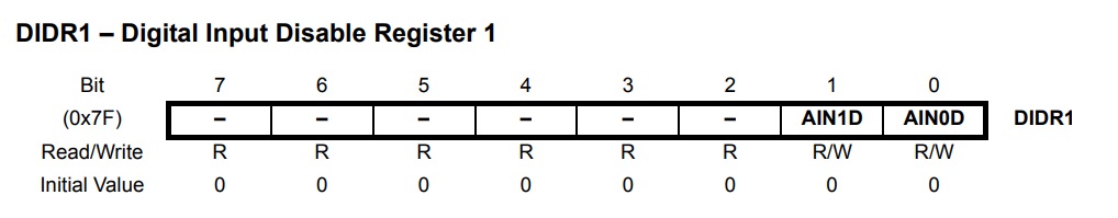
ในรูปที่ 3 ถึงรูปที่ 8 เป็นรีจิสเตอร์สำหรับกำหนดการทำงานของ Analog Comparator จะมีด้วยกัน 4 ตัวคือ ADCSRA, ADCSRB, ACSR และ DIDR1 โดยรายละเอียดของแต่ละบิตในรีจิสเตอร์สามารถอ่านเพิ่มเติมได้ในดาต้าชีตหน้า 202-204 และหน้า 218 และ 219 [Ref.7] สำหรับเนื้อหาถัดไปจะเป็นตัวอย่างการกำหนดการใช้งาน Analog Comparator ด้วยการเซตรีจิสเตอร์ต่างๆ และการนำไลบารี AnalogComp.h มาใช้งาน โดยใช้โปรแกรมจากเว็บไซต์อ้างอิงท้ายบทความ
 /*
  Arduino Code for Configuration Analog Comparator Register [Example.1]

  Arduino Code Program Ref. by
  https://www.hackster.io/yeshvanth_muniraj/analog-comparator-module-in-atmega328p-migrating-to-c-7502ea

  PIN AIN1,  D7 = Vref = 3.3V
  PIN AIN0, D6 = Input Voltage Adj
  PIN D13  = LED on Board
 */

 #include<avr/io.h>
 #define F_CPU 16000000UL

void setup() {
  pinMode(13,OUTPUT);
  ACSR = 0x00;            //  Register ACSR
  ADCSRB = 0x00;       //  Register ADCSRB
}

void loop() {
  if( (ACSR & 0x20) == 0)    // Check ACO (output bit)
  {
    digitalWrite(13, HIGH);   // turn the LED on
    delay(100);
  }
    digitalWrite(13, LOW);    // turn the LED off
    delay(100);
}
ตัวอย่างที่ 1 เป็นวิธีการกำหนดค่าในรีจิสเตอร์ ACSR และ ADCSRB ให้ทุกบิตมีค่าเท่ากับ 0 ทั้งหมด จากนั้นจะใช้การตรวจสอบตำแหน่งบิที่ 5 (ACO) ของรีจิสเตอร์ ACSR ในการณีที่บิต ACO เป็นลอจิก 0 ซึ่งหมายความว่าค่าแรงดันที่ขา AIN0 น้อยกว่า AIN1 เป็นผลให้แอลอีดี L (ขา D13) บนบอร์ดกระพริบให้ทราบ และเมื่อ AIN0 มากกว่า AIN1 แอลอีดี L ก็จะดับลง ซึ่งในตัวอย่างนี้จะไม่ใช้การอินเตอร์รัพท์ใดๆ
/*
Arduino Code for Configuration Analog Comparator Register [Example.2]

Arduino Code Program Ref. by
https://www.ee-diary.com/2021/07/arduino-analog-comparator-with-interrupt.html

*** pin AIN1 = D7  Vref. 3.3V
*** pin AIN0 = D6  Input Voltage Adj
*/

void setup () {
  pinMode(13, OUTPUT);
  Serial.begin(9600);

  DDRD |= (1<<PD4);
  DIDR1 |= (1<<AIN0D);  // Disable Digital Inputs at AIN0 and AIN1
  ADCSRA &= ~(1<<ADEN);
  ADCSRB |= (1<<ACME);  //Set ACME bit in ADCSRB to use external analog input at AIN1 -ve input
  ADMUX = 0x01; //select A1 as input
  ACSR =
  (0 << ACD) |    // Analog Comparator: Enabled
  (0 << ACBG) |   // Clear ACBG to use external input to AIN0 +ve input
  (0 << ACO) |    // Analog Comparator Output: OFF
  (1 << ACI) |    // Analog Comparator Interrupt Flag: Clear Pending Interrupt by setting the bit
  (1 << ACIE) |   // Analog Comparator Interrupt: Disabled
  (0 << ACIC) |   // Analog Comparator Input Capture: Disabled
  (0 << ACIS1) | (0 << ACIS0);   // Analog Comparator Interrupt Mode: Comparator Interrupt on Output Toggle

  sei();
}

void loop() {

  Serial.println(" LAB Analog Comparator ");
  digitalWrite(13, LOW);
  delay(100);
}

ISR(ANALOG_COMP_vect){

  if(ACSR & (1<<ACO))
  digitalWrite(13, HIGH);
  delay(100);
  Serial.println(" Interrup Analog Comparator");
}
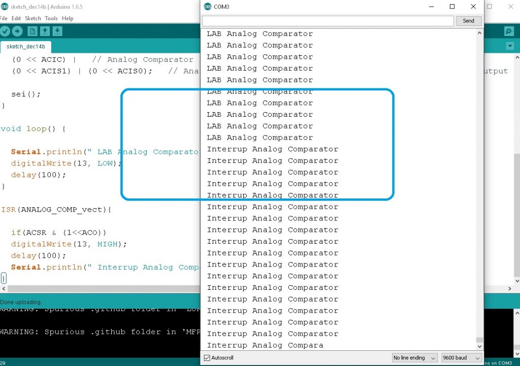
ตัวอย่างที่ 2 เป็นตัวอย่างอีกแบบหนึ่งที่จะเห็นรายละเอียดของการกำหนดบิตต่างๆ ในรีจิสเตอร์ ADCSRA, ADCSRB, ADMUX และ ACSR เป็นหลัก ซึ่งจะกำหนดใช้การอินเตอร์รัพท์เข้าช่วยโปรแกรมการงานหลักเพิ่มเติม ลักษณะการทำงานของโปรแกรมจะสังเกตเห็นว่าในกรณีที่ค่าแรงดันที่ขา AIN0 น้อยกว่า AIN1 เป็นผลให้แอลอีดี L (ขา D13) บนบอร์ดจะดับ แสดงข้อความ LAB Analog Comparator แต่เมื่อ AIN0 มากกว่า AIN1 เป็นผลให้เกิดการอินเตอร์รัพท์ไปยังตำแหน่ง ISR(ANALOG_COMP_vect) และแอลอีดี L ติด พร้อมทั้งแสดงข้อความ Interrup Analog Comparator ให้ทราบนั้นเอง
/*
Arduino Code for Configuration Analog Comparator Register [Example.3]

Arduino Code Program Ref. by
www.microcontrollerslab.com/arduino-comparator-tutorial

*** pin AIN1 = D7  Input Voltage Adj
*** pin AIN0 = D6  Internal Vref =1V
*/

// Definition of interrupt names
#include <avr/io.h>
// ISR interrupt service routine
#include <avr/interrupt.h>

const int pLED = 13; // LED at Pin13
const int pAIN1 = 7; // AIN1 at Pin7
volatile boolean iflag = true;
int idx;

// Install the interrupt routine for ACOMP
ISR(ANALOG_COMP_vect)
{
if ( ACSR & (1<<ACO) ) // ACO is set?
{
iflag = false;
digitalWrite(pLED, HIGH);
}
else
{
iflag = true;
digitalWrite(pLED, LOW);
}
}
void setup()
{
Serial.begin(9600);
pinMode(pLED, OUTPUT);
digitalWrite(pLED, LOW);
pinMode(pAIN1, INPUT);
cli();
ADCSRA &= ~(1<<ADEN); // ADC disabled
ADCSRB |= ~(1<<ACME); // AMUX enabled
ACSR = (1<<ACBG) | (1<<ACIE); // ACOMP Interrupt enabled
DIDR1 = (1<<AIN1D) | (1<< AIN0D);
sei();
Serial.print("ADCSRA: "); Serial.println(ADCSRA, HEX);
Serial.print("ADCSRB: "); Serial.println(ADCSRB, HEX);
Serial.print("ACSR: "); Serial.println(ACSR, HEX);
Serial.print("DIDR1: "); Serial.println(DIDR1, HEX);
Serial.println("Setup finished.");
}
void loop()
{
if (iflag)
Serial.println(idx); // iflag controls serial output
idx++;
delay(200);
}
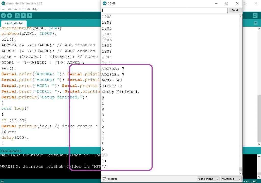
ตัวอย่างที่ 3 เป็นตัวอย่างการกำหนดบิตต่างๆ ในรีจิสเตอร์ ADCSRA, ADCSRB, DIDR1 และ ACSR และกำหนดใช้การอินเตอร์รัพท์เช่นกัน โดยเมื่อค่าแรงดันที่ขา AIN1 มากกว่า AIN0 จะแสดงการนับค่าตัวแปร idx ตลอดเวลา และเมื่อ AIN1 น้อยกว่า AIN0 จะทำให้เกิดการอินเตอร์รัพท์ขึ้น ที่ตำแหน่ง ISR(ANALOG_COMP_vect) เป็นผลให้แอลอีดี L (ขา D13) บนบอร์ดจะติดสว่างขึ้นแทนนั้นเอง
Arduino Library for AnalogComp.h
ตัวอย่างการใช้ไลบารี analogComp.h ข้างล่างนี้จะเป็นการใช้งานวงจร Analog Comparator ได้ง่ายขึ้น โดยเราเพียงศึกษาการใช้คำสั่งภาษา C++ เท่านั้น ซึ่งจะช่วยให้เราใช้เวลาในการพัฒนาโปรแกรมน้อยลง และจะนำตัวอย่างการใช้งานมา 3 แบบเพื่อให้เราสามารถนำไปใช้งานได้ตามที่ต้องการ
/*
Code program by : https://electronics.stackexchange.com/questions/376906/amplifying-pulse-signal-0-1-0-5v-to-arduino-digital-input

So, D7 is right (AIN0), at least it makes effect. Due that interrupt is raised when going over ~0.8V on that input. However A1 (signal input) voltage level, does not make any effect when interrupt is raised. Hmm, what could be the issue?

*** pin AIN1 = D7  Vref. 3.3V
*** pin AIN0 = D6  Input Voltage Adj
*/

#include "analogComp.h"

void setup() {
  analogComparator.setOn(AIN0, AIN1);  // AIN0 is on D7. As a reference voltage
  analogComparator.enableInterrupt(speedSensorInterrupt);
  Serial.begin(9600);
}

void loop()
{
   delay (100);
   Serial.println(".");
}

void speedSensorInterrupt()
{
   Serial.println("analog Comparator Interrupt Active");
}
ตัวอย่างที่ 4 ข้างบนจะเป็นตัวอย่างโปรแกรมอย่างง่าย ด้วยการประกาศการใช้งาน analogComparator.setOn(AIN0, AIN1); และการกำหนดให้เกิดการอินเตอร์รัพท์ด้วยคำสั่ง analogComparator.enableInterrupt(speedSensorInterrupt); ซึ่งเมื่อแรงดันที่ขา AIN0 มากกว่า AIN1 โปรแกรมการทำงานจะเข้าไปยังฟังก์ชันอินเตอร์รัพท์ speedSensorInterrupt นั้นเอง

/*

Code program by : https://github.com/leomil72/analogComp/tree/master

This is a simple sketch to demonstrate the use of analogComp, a
library to manage the analog comparator included in a wide
variety of Atmel microcontrollers

This sketch checks if the voltage on AIN0 will begin greater
than the voltage on AIN1. To test the sketch, build the following
circuit:
- connect pin D7 AIN1 to pin 3V3
- connect pin D6 AIN0 to GND using a pull-down resistor (10Kohm or greater)
- connect pin AIN0 to pin 5V to activate the comparation.
*/

#include "analogComp.h"

void setup() {
    //opens the serial comm
    Serial.begin(9600);
    delay(2000);
}

void loop() {
    //wait 5 seconds for AIN0 to begin greater than AIN1
    Serial.println(analogComparator.waitComp(), DEC);
}
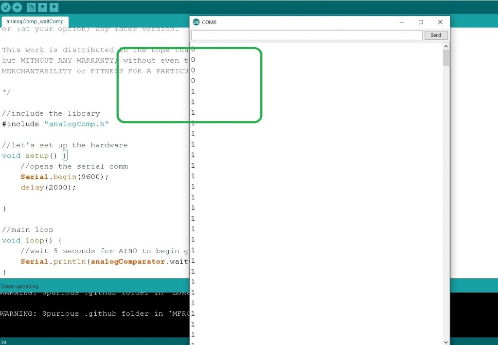
ตัวอย่างที่ 5 เป็นตัวอย่างโปรแกรมที่อยู่ในตัวอย่างไลบารี analogComp.h โดยการทำงานของโปรแกรมนี้จะส่งค่าตัวเลข 0 ไปยัง Serial Monitor เพื่อเป็นการรอให้แรงดันที่ขา AIN0 มากกว่า AIN1 ทุกๆ 5 วินาที และเมื่อค่าแรงดันที่ขา AIN0 มากกว่า AIN1 ก็จะทำให้โปรแกรมส่งค่าตัวเลข 1 แทนจนกว่าแรงดันที่ขา AIN0 น้อยกว่า AIN1 นั้นเอง ผลการทดลองแสดงในรูปที่ ในกรอบสีเขียว
/*

Code program by : https://github.com/leomil72/analogComp/tree/master

This is a simple sketch to demonstrate the use of analogComp, a
library to manage the analog comparator included in a wide
variety of Atmel microcontrollers

This sketch enables an interrupt to be raised when on the analog input 0
(pin AIN0) there is a voltage greater than the voltage on the
analog input 1 (pin AIN1). To test the sketch, build the following
circuit:
- connect pin D7 AIN1 to pin 3V3
- connect pin D6 AIN0 to GND using a pull-down resistor (10Kohm or greater)
- connect pin AIN0 to pin 5V to activate the interrupt
*/

#include "analogComp.h"

const byte LED13 = 13; //set the output LED
volatile boolean enableLed = false; //used to check if the interrupt has raised

void setup() {
    pinMode(LED13, OUTPUT); //LED pin as output
    analogComparator.setOn(AIN0, AIN1); //we instruct the lib to use voltages on the pins
    analogComparator.enableInterrupt(changeStatus, CHANGE); //we set the interrupt and when it has to be raised
}

void loop() {
    if (enableLed) { //let's check if the analog comparator has raised the interrupt
        //yes, so we do a little blink of the LED
        digitalWrite(LED13, HIGH);
        delay(200);
        digitalWrite(LED13, LOW);
        enableLed = false;
    }
}

//interrupt to be raised by the analog comparator
void changeStatus() {
    enableLed = true; //let's inform the main loop that the condition has been reached by the analog comparator
}
ตัวอย่างที่ 6 เป็นตัวอย่างโปรแกรมที่อยู่ในไลบารี analogComp.h เช่นกัน โดยในช่วงเวลาปกติโปรแกรมจะทำงานในชุดคำสั่ง void loop() ตลอดเวลาโดยจะสังเกต LED ที่ขา D13 บนบอร์ด Arduino UNO จะดับตลอดเวลา ด้วยการกำหนดให้ค่าตัวแปร enableLed = false; และเมื่อแรงดันที่ขา AIN0 มากกว่า AIN1 ทำให้เกิดการอินเตอร์รัพท์ขึ้น เป็นผลให้โปรแกรมกระโดดมายังโปรแกรมอินเตอร์รัพท์ void changeStatus() เพื่อกำหนดค่าตัวแปร enableLed = true; โดยในขณะนี้ LED ที่ขา D13 ก็จะกระพริบให้ทราบทันที
สำหรับการทดลองใช้งานออปแอมป์ภายในตัวชิฟไมโครคอนโทรลเลอร์ ATMEGA328P นี้ เป็นการใช้งานฮาร์ดแวร์ภายในตัวชิฟที่มีมาให้อีกส่วนหนึ่ง ซึ่งเราสามารถเลือกนำมาใช้งานต่างๆ ได้อีกรูปแบบหนึ่ง ทั้งนี้ในงานที่ไม่ต้องการประมวลผลค่าแรงดันอินพุตอะนาลอกตลอดเวลา (ตำแหน่งขา A0-A5) ก็จะช่วยให้ตัวไมโครคอนโทรลเลอร์ทำงานในโปรแกรมหลัก (void loop()) ได้มีประสิทธิภาพมากขึ้น
Reference
- https://microcontrollerslab.com/arduino-comparator-tutorial/
- https://github.com/leomil72/analogComp/blob/master/examples/analogComp_enableInterrupt/analogComp_enableInterrupt.ino
- https://forum.arduino.cc/t/analog-comparator-and-hardware-pwm/877417/7
- https://www.ee-diary.com/2021/07/arduino-analog-comparator-with-interrupt.html
- https://www.hackster.io/yeshvanth_muniraj/analog-comparator-module-in-atmega328p-migrating-to-c-7502ea
- https://electronics.stackexchange.com/questions/376906/amplifying-pulse-signal-0-1-0-5v-to-arduino-digital-input
- https://ww1.microchip.com/downloads/en/DeviceDoc/Atmel-7810-Automotive-Microcontrollers-ATmega328P_Datasheet.pdf
- https://forum.arduino.cc/t/arduino-uno-pinout-diagram/142856