AD9833 Programmable Waveform Generator with Arduino UNO
การทดลองใช้งานงานโมดูล GY-9833 กับการสร้างสัญญาณในรูปแบบต่างๆ หรือเรียก ฟังก์ชั่นเจนเนอร์เรเตอร์ (Programmable Waveform Generator) ซึ่งภายในโมดูลจะใช้ไอซีเบอร์ AD9833 ในการประมวลผลที่สามารถโปรแกรมการทำงานได้ โดยในการทดลองจะเชื่อมต่อกับบอร์ดควบคุม Arduino UNO ซึ่งตัวโมดูลตัวนี้จะมีขนาดที่ค่อนข้างเล็ก ควบคุมการทำงานได้ง่ายด้วยการสื่อสารแบบ SPI Protocol ที่ความละเอียดขนาด 28 บิต สามารถสร้างสัญญาณต่างๆ ได้ในช่วง 0Hz-12.5MHz ในรูปแบบสัญญาณโซน์เวฟ (Sinusoidal wave) สัญญาณสามเหลี่ยม (Triangular wave) และสัญญาณพัลซ์สี่เหลี่ยม (Square wave)
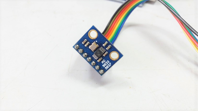
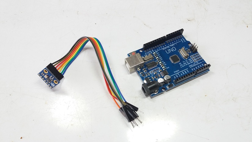
รูปที่ 1 และรูปที่ 2 แสดงลักษณะของโมดูล GY-9833 ที่นำมาทดลองโครงงานซึ่งมีขนาดเล็กสามารถเชื่อมต่อกับบอร์ดควบคุมไมโครคอนโทรลเลอร์ต่างๆ ได้ทันที โดยในรูปที่ 2 จะเป็นการเตรียมบอร์ดควบคุม Arduino UNO ที่สามารถหาซื้อได้ง่ายและราคาไม่แพง
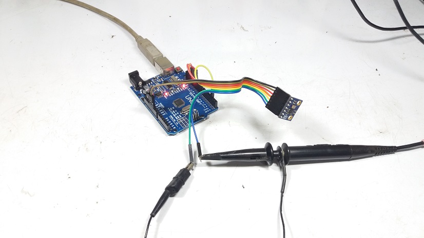
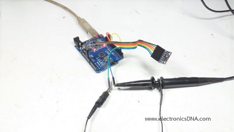
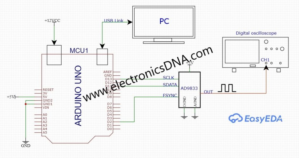
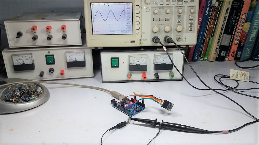
รูปที่ 3 เป็นการต่ออุปกรณ์ร่วมกันระหว่างบอร์ดควบคุม Arduino UNO และโมดูล GY-9833 ในการทดลอง โดยที่ขาเอาต์พุตของโมดูลจะใช้สายโพรบของออสซิลโลสโคปวัดสัญญาณได้โดยตรง ซึ่งในการทดลองจะใช้ไฟเลี้ยงจากพอร์ต USB (+5V) ก็สามารถทำงานได้เป็นปกติ
/*
AD9837 Pro Generator sample code
This was written in Arduino 1.0.1,
for an Arduino Pro Mini, 5V, 16MHz
Pete Dokter, 9/2/12

With this code running, open up a teminal window at 9600 baud,
enter your desired frequency followed by <enter>. The code translates
the ascii characters and sets the frequency on the AD9837.

The connections to the AD9837 board are:

FSYNC -> 2
SCLK -> 13 (SCK)
SDATA -> 11 (MOSI)

+Vin = VCC on Pro Micro
GND -> GND

This code bears the license of the beer. If you make money off of this,
you gotta beer me.
*/

#define FSYNC 2
#define SDATA 11
#define SCLK 13

long freq;
void AD9837Write(char cmd, char dat);
void set_freq(long frequency);
unsigned char flag_type = 0;

void setup()
{
  pinMode(FSYNC, OUTPUT);
  pinMode(SDATA, OUTPUT);
  pinMode(SCLK, OUTPUT);
  Serial.begin(9600);
  digitalWrite(FSYNC, HIGH);
  digitalWrite(SDATA, HIGH);
  digitalWrite(SCLK, HIGH);
 String help  = "<----Command---->\r\n";
        help += "Set sine wave -- sine freq\r\n";
        help += "Ex. set sine wave @1Mhz--> sin 1000000\r\n";
        help += "Set set triangular wave -- tri freq\r\n";
        help += "Ex. set triangular wave @100Khz--> tri 100000\r\n";
        help += "Set set square --  sqr freq\r\n";
        help += "Ex. set square wave @2Khz--> sqr 2000\r\n";
 Serial.println(help);
  set_freq(100);
}

void loop()
{
  if(Serial.available())
  {
      String req = Serial.readStringUntil('\n');
      if(req.indexOf(F("sin")) != -1)
      {
          flag_type=0;
          set_freq(freq_str_to_long(req));
      }
      if(req.indexOf(F("sqr")) != -1)
      {
          flag_type=1;
          set_freq(freq_str_to_long(req)*2);
      }
      if(req.indexOf(F("tri")) != -1)
      {
          flag_type=2;
          set_freq(freq_str_to_long(req));
      }
  }
 }
long freq_str_to_long(String dat)
{
    char index1 = dat.indexOf(F(" "));
    return(dat.substring(index1+1).toInt());
}
void set_freq(long frequency)
{
  //
  int MSB;
  int LSB;
  int phase = 0;

  //We can't just send the actual frequency, we have to calculate the "frequency word".
  //This amounts to ((desired frequency)/(reference frequency)) x 0x10000000.
  //calculated_freq_word will hold the calculated result.
  long calculated_freq_word;
  float AD9837Val = 0.00000000;

  AD9837Val = (((float)(frequency))/25000000);
  calculated_freq_word = AD9837Val*0x10000000;

  /*
  Serial.println("");
  Serial.print("Frequency word is ");
  Serial.print(calculated_freq_word);
  Serial.println("");
  */

  //Once we've got that, we split it up into separate bytes.
  MSB = (int)((calculated_freq_word & 0xFFFC000)>>14); //14 bits
  LSB = (int)(calculated_freq_word & 0x3FFF);

  //Set control bits DB15 ande DB14 to 0 and one, respectively, for frequency register 0
  LSB |= 0x4000;
  MSB |= 0x4000;

  //set for 5KHz
  //LSB = 0x47AE;
  //MSB = 0x4005;

  //set for 10KHz
  //LSB = 0x4F5C;
  //MSB = 0x400A;

  //set for ?
 // LSB = 0x6F5C;
  //MSB = 0x40F5;

  phase &= 0xC000;

  AD9837Write(0x2100);

 delay(100);
  //Set the frequency==========================
  AD9837Write(LSB);  //lower 14 bits
  AD9837Write(MSB);  //upper 14 bits
  AD9837Write(phase);  //mid-low
  delay(10);

  switch(flag_type)
  {
    case 0:
      AD9837Write(0x2000); // sin
      Serial.print("Sine ");
    break;
    case 1:
      AD9837Write(0x2020); // square
      Serial.print("Square ");
      frequency = (frequency/2);
    break;
    case 2:
      AD9837Write(0x2002); // triangle
      Serial.print("Triangle ");
    break;
  }
  Serial.print(frequency);
  Serial.println(" Hz");
}

//This is the guy that does the actual talking to the AD9837
//via bit-bang SPI...
void AD9837Write(int dat)
{
  int x;
  digitalWrite(FSYNC, LOW);  //Set FSYNC low
  for (x = 0; x < 16; x++)
  {
    if (dat & 0x8000)
    {
    digitalWrite(SDATA, HIGH);   //Set SDATA according to MSB in cmd
    }
    else
   {
    digitalWrite(SDATA, LOW);
   }
    digitalWrite(SCLK, LOW);  //CLK transistion to latch the bit into the AD9835
    digitalWrite(SCLK, HIGH);
    dat <<= 1;  //Shift to next bit in cmd
  }
  digitalWrite(FSYNC, HIGH);  //Set FSYNC high
}
สำหรับโปรแกรมที่แสดงข้างบนนี้ (Code Program Arduino) เป็นโปรแกรมที่สามารถโปรแกรมให้กับบอร์ด Arduino UNO ได้ทันทีโดยไม่ใช้ไลบราลีเพิ่มเติม (Arduino Library) ซึ่งผู้พัฒนาโปรแกรมนี้คือ Pete Dokter และผู้อ่านสามารถปรับแต่งโปรแกรมให้สามารถนำไปใช้งานในด้านต่างๆ ตามที่ต้องการ
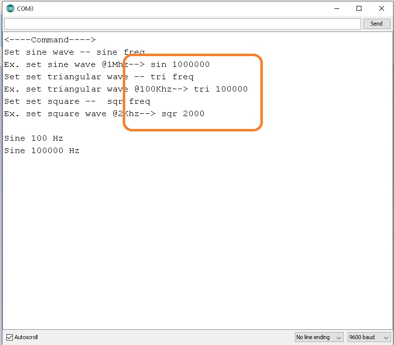
ในรูปที่ 4 แสดงตัวอย่างการป้อนค่าให้กับบอร์ดควบคุม Arduino UNO สำหรับเป็นคำสั่งในการสร้างสัญญาณต่างๆ โดยในรูปจะเห็นตัวอย่างในกรอบสี่เหลี่ยมสีส้ม เช่น ต้องการสร้างสัญญาณพัลซ์สี่เหลี่ยมที่ความถี่ 1000kHz จะใช้คำสั่ง sqr 1000 โดยให้เราป้อนที่ช่อง SEND (ข้างบน) และตามด้วยกด Enter ซึ่งหลังจากที่เราป้อนแล้วโปรแกรมจะมีข้อความตอบกลับให้ทราบ
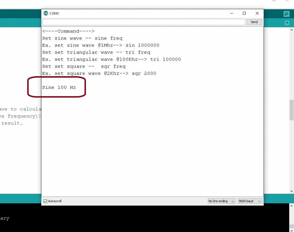
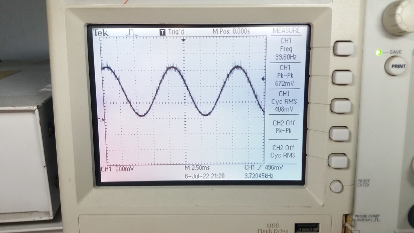
รูปที่ 5 และรูปที่ 6 เป็นการทดลองให้โมดูล GY-9833 สร้างสัญญาณไซน์เวฟที่ความถี่ 100Hz (ความถี่ต่ำ) และสังเกตสัญญาณที่เกิดขึ้น
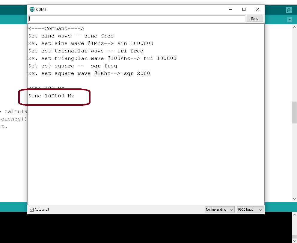
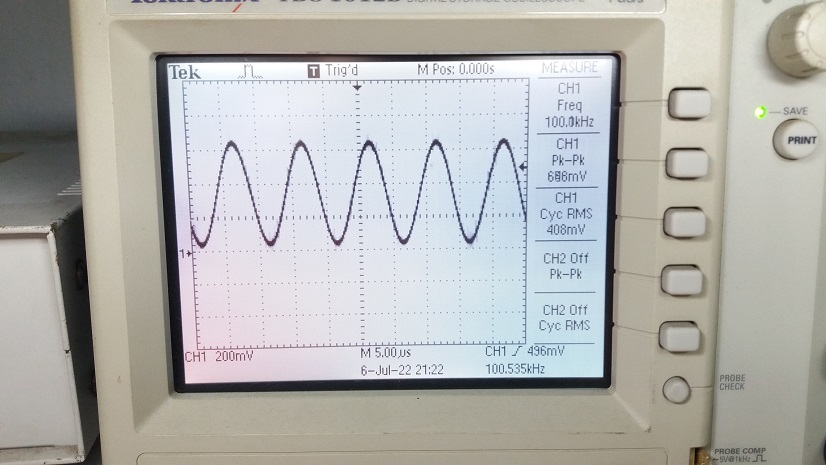
ในรูปที่ 7 และรูปที่ 8 เป็นการทดลองให้โมดูล GY-9833 สร้างสัญญาณไซน์เวฟที่ความถี่ 100kHz (ความถี่สูง) จากนั้นสังเกตลักษณะของสัญญาณที่เกิดขึ้นอีกครั้ง
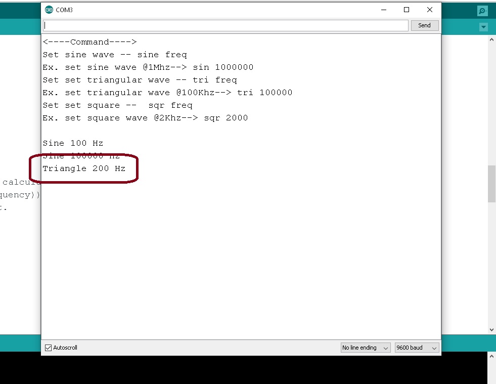

ต่อมาในรูปที่ 9 และรูปที่ 10 เป็นการทดลองให้โมดูลสร้างสัญญาณสามเหลี่ยมที่ความถี่ 200Hz (ความถี่ต่ำ) และสังเกตสัญญาณที่เกิดขึ้น
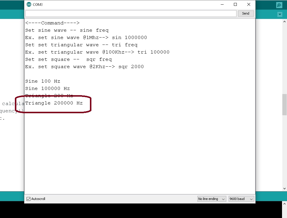
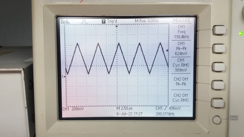
ในรูปที่ 11 และรูปที่ 12 เป็นการทดลองให้โมดูล GY-9833 สร้างสัญญาณสามเหลี่ยมที่ความถี่ 200kHz (ความถี่สูง) อีกครั้ง จากนั้นสังเกตลักษณะของสัญญาณที่เกิดขึ้น
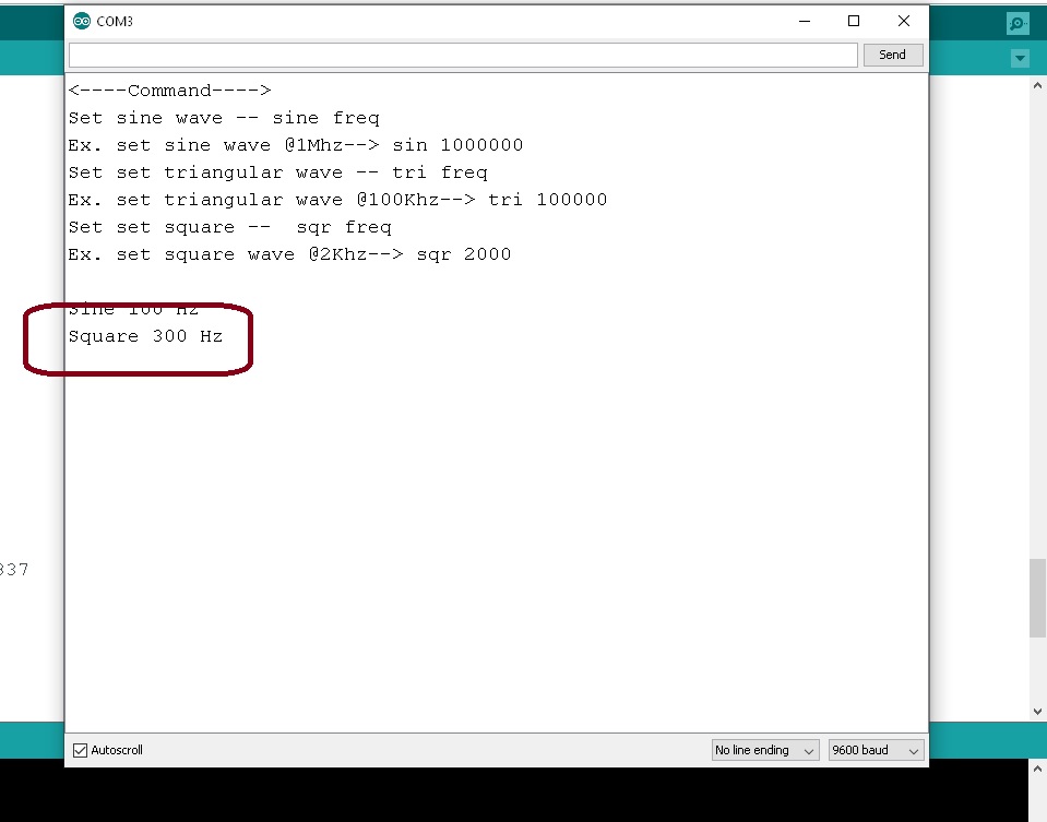
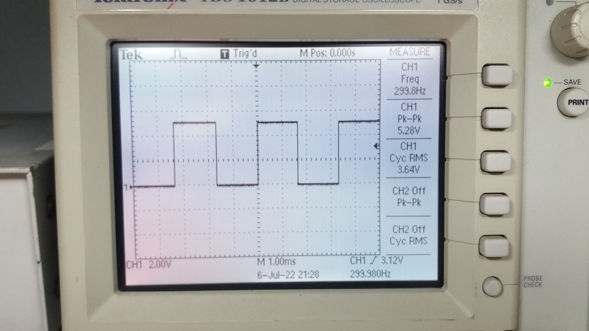
สำหรับรูปที่ 13 และรูปที่ 14 เป็นการทดลองให้โมดูลสร้างสัญญาณสี่เหลี่ยมความถี่ 300Hz (ความถี่ต่ำ) และสังเกตสัญญาณที่เกิดขึ้น
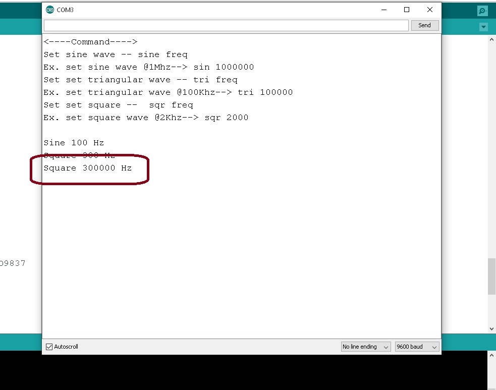
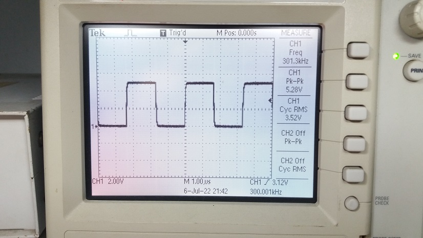
ในรูปที่ 15 และรูปที่ 16 เป็นการทดลองให้โมดูล GY-9833 สร้างสัญญาณสามเหลี่ยมที่ความถี่ 300kHz (ความถี่สูง) และสังเกตลักษณะของสัญญาณที่เกิดขึ้น การทดลองวัดสัญญาณทั้ง 3 แบบนั้นจะเห็นว่าแอมปริจูดของสัญญาณจะไท่เท่ากัน ดังนั้นแนะนำให้ออกแบบวงจรขยายสัญญาณเพิ่มเติมด้วยออปแอมป์ให้ได้ขนาดตามที่ต้องการนำไปใช้งานอีกครั้ง
กับโครงงานการสร้างสัญญาณฟังก์ชั่นเจนเนอร์เรเตอร์ด้วยโมดูล GY-9833 เป็นโครงงานเล็กๆ ซึ่งในบางครั้งเราอาจจะต้องใช้งานบ้าง เพื่อทำการทดลองแหล่งจ่ายไฟเลี้ยงแบบสวิตชิ่ง เพาเวอร์ซัพพลาย (Switching power supply) หรือวงจรดีซี ทู ดีซี คอนเวอร์เตอร์ (DC-to-DC converter) เป็นต้น ทั้งนี้จะช่วยให้เราสามารถทดลองวงจรด้วยการปรับความถี่สวิตชิ่งที่ความถี่ต่างๆ ได้ง่ายและปรับเลือกรูปแบบสัญญาณต่างๆ ในการทดลองได้ 3 รูปแบบ นอกจากนี้ยังเป็นวงจรที่สร้างได้ง่ายและราคาไม่แพงมากนักครับ.
Reference
- https://www.analog.com/media/en/technical-documentation/data-sheets/ad9833.pdf
- https://github.com/BasicCode/AD9833-arduino
- https://github.com/annem/AD9837/blob/master/PetesProGenExample/PetesProGenExample.ino
- https://github.com/y-x-c/wearable-microphone-jamming/issues/6
- https://github.com/Billwilliams1952/AD9833-Library-Arduino/blob/master/examples/AD9833_test_suite/AD9833_test_suite.ino
- https://www.electroniclinic.com/ad9833-programmable-waveform-generator-using-arduino/
- https://www.teachmemicro.com/arduino-ad9833-signal-generator/
- https://www.instructables.com/Portable-Function-Generator-on-Arduino/
- https://electronics.stackexchange.com/questions/226695/ad9833-problems-with-arduino-and-spi-cant-think-of-a-good-title
- https://leap.tardate.com/playground/ad9833/basicdemocycle/
- https://www.instructables.com/Signal-Generator-AD9833/