Simple MPPT DC-DC Buck Converter with Arduino MEGA1280 [EP1]
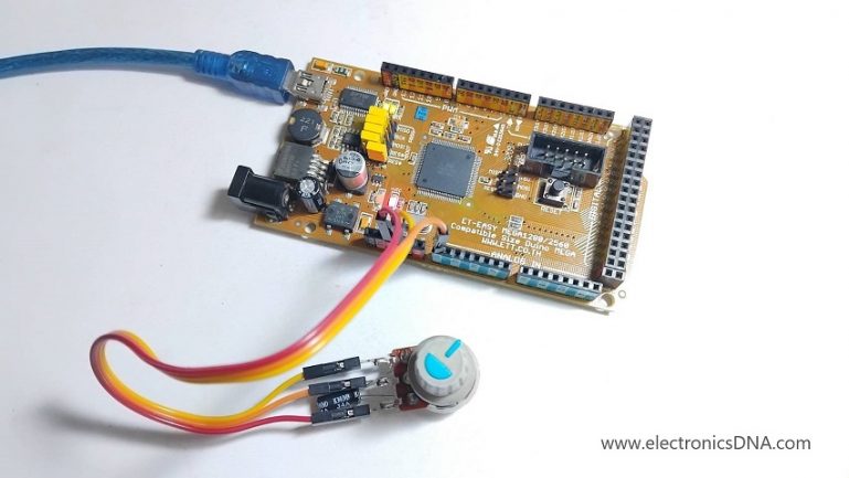
โครงงานนี้เป็นการทดลองสร้างวงจร MPPT DC-DC ฺBuck Converter ขนาดเล็ก สำหรับศึกษาระบบการทำงานในเรื่องโปรแกรมคำสั่งการติดตามจุดกำลังไฟฟ้าสูงสุด, อัลกอริทึมในการตรวจจับและติดตามจุด MPP แบบเรียลไทม์, ประสิทธิภาพการทำงาน, ความยืดหยุ่นในการใช้งานและลดการสูญเสียในสายไฟที่ใช้งาน ทั้งนี้วัตถุประสงค์หลักของการใช้ MPPT techniques เพื่อเพิ่มประสิทธิภาพการใช้พลังงานสูงสุด จากแหล่งกำเนิดไฟฟ้าที่ไม่คงที่ เช่น แผงโซลาร์เซลล์ไปยังอุปกรณ์ปลายทาง เช่น แบตเตอรี่หรือระบบไฟฟ้าอื่นๆ เป็นต้น
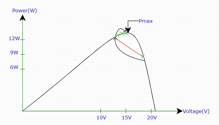
รูปที่ 1 แสดงค่า Power-Voltage curve at a radiation หรือ “กราฟความสัมพันธ์ระหว่างกำลังไฟฟ้า-แรงดันไฟฟ้า” (P-V Curve) ซึ่งเป็นความสามารถในการผลิตกำลังไฟฟ้า (P) ของแผงโซลาร์เซลล์ (หรือเซลล์แสงอาทิตย์) ที่ค่าแรงดันไฟฟ้า (V) ต่างๆ ภายใต้ระดับความเข้มของแสงอาทิตย์ (Irradiance) และอุณหภูมิที่กำหนด
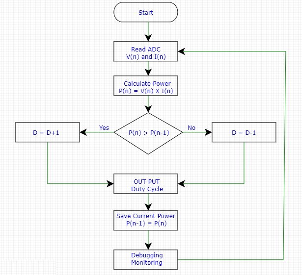
รูปที่ 2 แสดงโฟลวชาร์ตการทำงานของโปรแกรม MPPT techniques เบื้องต้น ซึ่งในรูปจะเห็นกระบวนการทั้งหมด 6 ส่วน คือ ส่วนแรกจะเป็นอ่านค่าแรงดัน V(n) และกระแส I(n) ที่ได้จากแผงโซล่าเซลล์ ส่วนที่สองจะเป็นการคำนวณค่าพลังงานไฟฟ้าที่ผลิตได้จากแผงโซล่าเซลล์จาก P(n) = V(n)xI(n) สำหรับประมวลผล ส่วนที่สามจะเป็นการตรวจสอบว่าค่าพลังงานไฟฟ้าที่อ่านได้ปัจจุบัน P(n) มีค่ามากกว่าค่าพลังงานไฟฟ้าที่อ่านได้ก่อนหน้านี้หรือไม่ P(n-1) โดยในกรณีที่ค่าพลังงานไฟฟ้าปัจจุบัน P(n) มีค่ามากกว่าค่าพลังงานไฟฟ้าที่อ่านได้ก่อนหน้าจะทำการเพิ่มค่าดิวตี้ไซเกิลอีก 1 (การเพิ่มค่าดิวตี้ไซเกิลอาจจะปรับค่าใหม่ได้ตามความเหมาะสมภายหลัง เช่น 1,2,3,4 และ 5) ด้วยคำสั่ง (D=D+1) ต่อมาในกรณีที่ค่าพลังงานไฟฟ้าปัจจุบัน P(n) มีค่าน้อยกว่าค่าพลังงานไฟฟ้าที่อ่านได้ก่อนหน้าจะทำการลดค่าดิวตี้ไซเกิลลง 1 ด้วยคำสั่ง (D=D-1) หรือในกรณีที่ค่าพลังงานไฟฟ้าปัจจุบัน P(n) และค่าพลังงานไฟฟ้าที่อ่านได้ก่อนหน้าเท่ากันก็จะให้คงค่าดิวตี้ไซเกิลเดิมไว้ ในส่วนที่สี่ จะเป็นการกระทำคำสั่งเปลี่ยนค่าดิวตี้ไซเกิลให้กับตัวประมวลผลทันที ส่วนที่ห้าเมื่อเปลี่ยนค่าดิวตี้ไซเกิลแล้ว จะเป็นการเก็บค่าพลังงานไฟฟ้าปัจจุบัน P(n) ไว้ที่ ค่าพลังงานไฟฟ้าก่อนหน้านี้ P(n-1) สุดท้ายในส่วนที่หกจะเป็นการแสดงค่าแรงดัน, กระแส, พลังงานไฟฟ้า และค่าดิวตี้ไซเกิลที่เกิดขึ้นสำหรับตรวจสอบการทำงานด้วยคำสั่ง (Debugging/Monitoring)
// Simple MPPT DC-DC Converter //

// --- Global Variables ---
//     Pin Definitions

const int PWM_PIN = 9;         // The Arduino pin (e.g., Pin 9 or 10 on Uno for Timer1)
const int VIN_PIN = A0;        // Analog pin for Solar Panel Voltage sensing
const int IIN_PIN = A1;        // Analog pin for Solar Panel Current sensing
const int addLED = 13;         // Display for Power increased

// MPPT Variables
int pwm = 128;            // Initial PWM duty cycle (0-255 for 8-bit timer)
int delta = 3;            // Small step size for changing the PWM
int Power_now = 0;
int Power_anc = 0;        // "anc" stands for 'previous' or 'ancient'
int Vin = 0;
int Iin = 0;

// ---------------------------------------------

void setup() {
  pinMode(PWM_PIN, OUTPUT);
  pinMode(addLED, OUTPUT);
  Serial.begin(9600);

  // --- HIGH-FREQUENCY PWM SETUP (CRITICAL FOR DC-DC CONVERTER) ---
  // A standard analogWrite() is too slow.
  // This example sets Timer1 on an Uno (Pins 9 and 10) to Fast PWM mode with no prescaler (~31.25 kHz)
  TCCR1B = (TCCR1B & 0xF8) | 0x01;
  TCCR1A = (TCCR1A & 0xFC) | 0x02;
  analogWrite(PWM_PIN, pwm); // Start PWM at the initial duty cycle
}

void loop() {

  // 1. Read and Scale Input Values

  //float Vin = analogRead(VIN_PIN) * VOLTAGE_SCALE;
  //float Iin = analogRead(IIN_PIN) * CURRENT_SCALE;

  // 2. Calculate Current Power
    //Power_now = Vin * Iin;

  // 3. MPPT - Perturb and Observe (P&O) Algorithm

      Power_now = analogRead(VIN_PIN);   //  Test Power now

  // Power increased
  if (Power_now > Power_anc) {pwm += delta; digitalWrite(13, HIGH);delay(100);digitalWrite(13, LOW);}
  // Power decreased
  if (Power_now < Power_anc) {pwm -= delta; delay(100);}

  // 4. Update the PWM Output
  // Constrain the PWM value to prevent overflow and protect the circuit (0 to 255)
     pwm = constrain(pwm, 10, 245); // Added a small margin from 0 and 255
     analogWrite(PWM_PIN, pwm);

  // 5. Save the Current Power for the next cycle
     Power_anc = Power_now;

  // 6. Optional: Print values for debugging/monitoring
     //Serial.print("Vin: "); Serial.print(Vin);
     //Serial.print("V, Iin: "); Serial.print(Iin);
     Serial.print(" Power: "); Serial.print(Power_now);
     Serial.print("W, PWM: "); Serial.println(pwm);
     delay(200); // Wait 200ms before the next perturbation
}
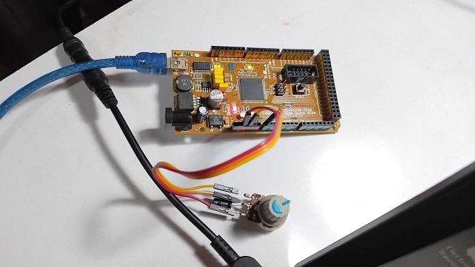

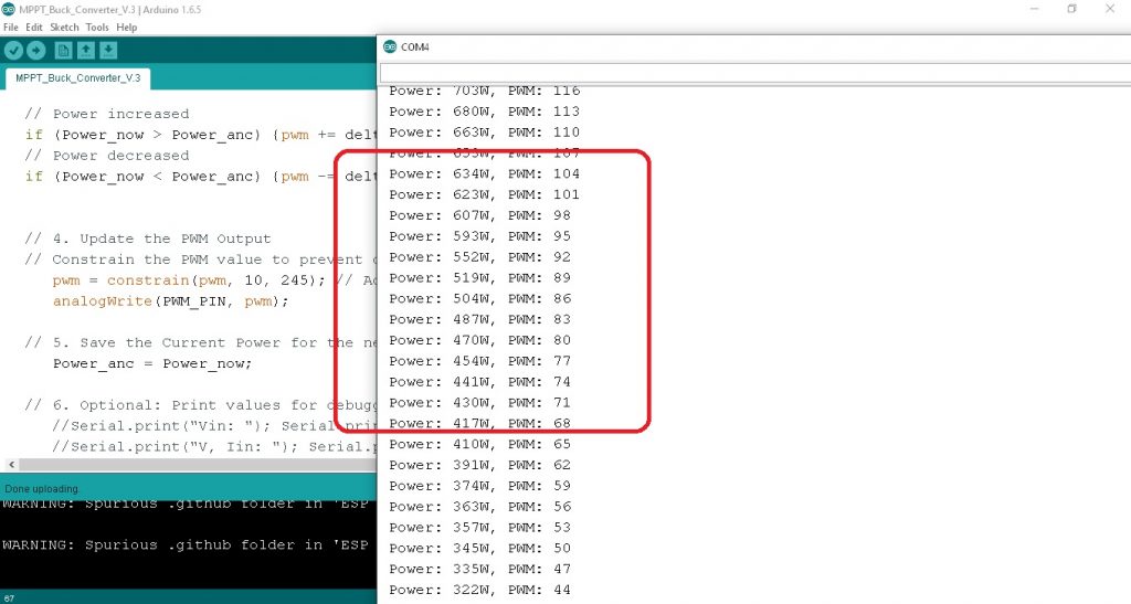
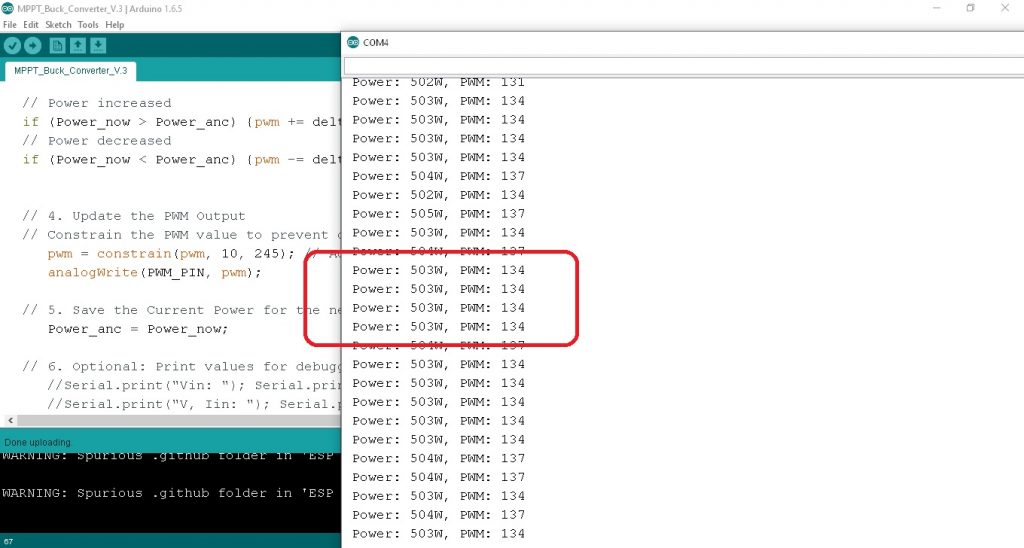
ในรูปที่ 4 ถึงรูปที่ 6 เป็นการทดลองปรับค่า VR ที่ต่อขา A0 แทนค่า Power ที่เปลี่ยนแปลงจริง โดยจะทดลองปรับค่า VR ในกรณี P(n) > P(n-1) กรณี P(n) < P(n-1) และ P(n) = P(n-1) ซึ่งจะกำหนดค่า delta = 3 ตามลำดับ ทั้งนี้โครงงานในตอนที่ 1 นี้จะเป็นศึกษาเกี่ยวกับกราฟแสดง Power-Voltage curve, โฟลวชาร์ตการทำงานของโปรแกรม MPPT techniques, โปรแกรมคำสั่ง C++ สำหรับบอร์ดควบคุม Arduino Mega1280 และผลการทดลองการทำงานของโปรแกรมให้เป็นไปตามเงื่อนไขที่กำหนดและทำงานได้ถูกต้องเพื่อนำไปใช้ในในวงจรจริงในตอนต่อไป
Reference
- https://www.ti.com/lit/ug/tidu404/tidu404.pdf
- https://www.researchgate.net/publication/330653338_DC-DC_Boost_Converter_Design_for_Fast_and_Accurate_MPPT_Algorithms_in_Stand-Alone_Photovoltaic_System
- https://www.researchgate.net/figure/Electronic-diagram_fig11_303563850
- https://www.researchgate.net/figure/Flowchart-of-conventional-HC-MPPT_fig10_303563850
- https://www.researchgate.net/figure/Flow-diagram-of-the-perturb-and-observe-P-O-algorithm_fig1_366942234
- https://pdfs.semanticscholar.org/d99a/94f1110d6e68d85c90547ea877aefd8fb53f.pdf
- https://ijarsct.co.in/Paper5700.pdf
- https://www.ijareeie.com/upload/2013/december/25_2Copies_DCToDC.pdf
- https://www.researchgate.net/figure/Searching-strategy-of-conventional-P-O-MPPT-algorithm_fig3_354901321
- https://www.researchgate.net/figure/Flowchart-of-P–O-based-MPPT-Algorithm_fig1_360395692