Simple I2C Communication with Arduino to Arduino Board

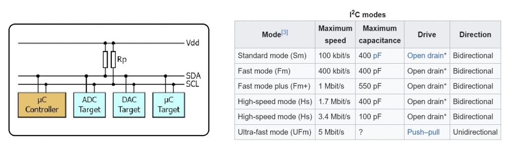
โครงงานนี้เป็นการทดลองสื่อสารกันระหว่างบอร์ด Arduino กับ Arduino ด้วยการสื่อสารแบบ I2C (Inter-Integrated Circuit) สำหรับเป็นการศึกษารูปแบบคำสั่งโปรแกรม Arduino IDE และการต่อวงจรระหว่างบอร์ดควบคุมเข้าด้วยกัน ทั้งนี้จุดเด่นของการสื่อสารแบบ I2C จะสามารถรับและส่งข้อมูลระหว่างกันได้ค่อนข้างสูงและอุปกรณ์อิเล็กทรอนิกส์ต่างๆ ก็นิยมใช้การสื่อสารแบบ I2C มากขึ้น เช่น เซนเซอร์อุณหภูมิ, เซนเซอร์วัดความเร่ง, ไอซีตัวแปลงสัญญาณอนาล็อกเป็นดิจิตอล เป็นต้น ดังนั้นการทดลองในโครงงานนี้จะเป็นความรู้เบื้องต้นในการเรียนรู้นำไปใช้งานต่อไป
/*
 Test LAB1 : Code Arduino for Master
*/

#include <Wire.h>

void setup()
{
  Wire.begin();
}

int add = 0;

void loop()
{
  Wire.beginTransmission(10);  // Address is 10
  Wire.write(" Master send is ");
  Wire.write(add);
  Wire.endTransmission();

  add++;
  delay(100);
}
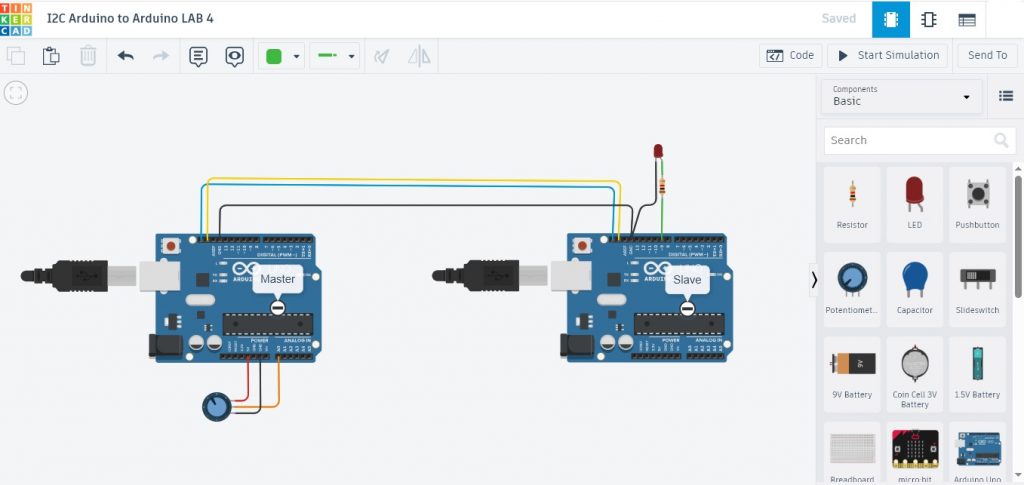
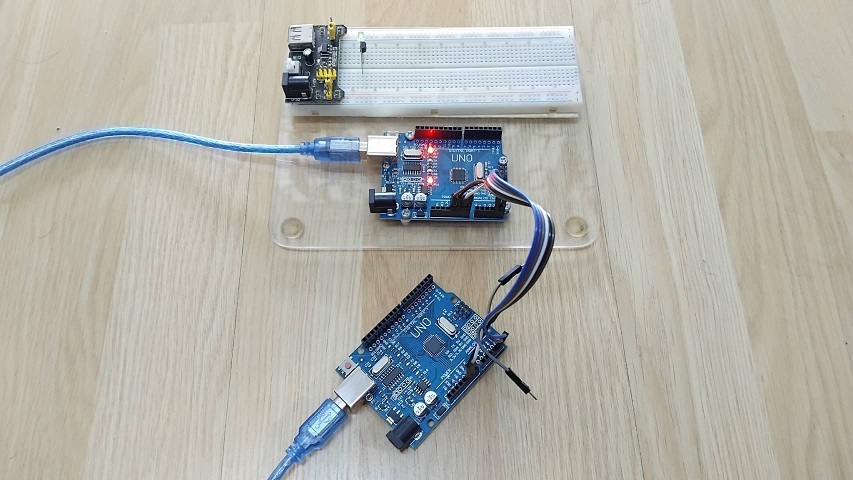
รูปที่ 2 แสดงลักษณะของการต่อวงจรสำหรับทดลองการสื่อสารแบบ I2C ด้วยบอร์ดระหว่าง Arduino UNO และ Arduino UNO ในการทดลองที่ 1 จะสังเกตเห็นว่าที่ตำแหน่งขา A4: SDA, A5: SCL และ GND จะเชื่อมต่อเข้ากันโดยตรง จากนั้นทำการโปรแกรมคำสั่งสำหรับ Arduino UNO ตัวที่ 1 (ด้านซ้ายมือ Master) สำหรับส่งตัวอักษร (Master send is) และข้อมูลค่าตัวแปร (add) ไปยังบอร์ดรับที่ระบุหมายเลข 10 (Address is 10) ด้วยโปรแกรมที่แสดงข้างบนนี้ (Test LAB1 : Code Arduino for Master)
/*
    Test LAB1 : Code Arduino for Slave
*/

#include <Wire.h>

void setup()
{
  Wire.begin(10); // Address is 10
  Wire.onReceive(receiveEvent);
  Serial.begin(9600);
  pinMode(13, OUTPUT);
}

void loop()
{
  digitalWrite(13, HIGH);
  delay(200);
  digitalWrite(13, LOW);
  delay(200);
}

void receiveEvent(int howMany)
{
  while(1 < Wire.available())
  {
    char c = Wire.read();
    Serial.print(c);          // print the character
  }
    int add = Wire.read();    // receive byte as an integer
    Serial.println(add);      // print the integer
}
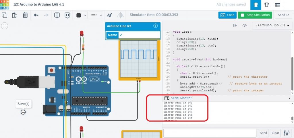
สำหรับโปรแกรม (Test LAB1 : Code Arduino for Slave) ที่แสดงข้างบน จะทำหน้าที่รับตัวอักษร (Master send is) และข้อมูลค่าตัวแปร (add) ที่ระบุหมายเลขบอร์ดรับเป็นค่า 10 เมื่อมีการส่งข้อมูลต่างๆ มา โดยใช้คำสั่ง void receiveEvent(int howMany) ในการตรวจสอบ และในกรณีที่มีข้อมูลเข้ามา โปรแกรมแสดงผลด้วยคำสั่ง Serial.print(c); และ Serial.println(add); โดยในช่วงเวลาช่วงเวลาปกติแอลอีดี (D13) บนบอร์ด Arduino จะกระพริบให้ทราบสถานะการทำงานอยู่
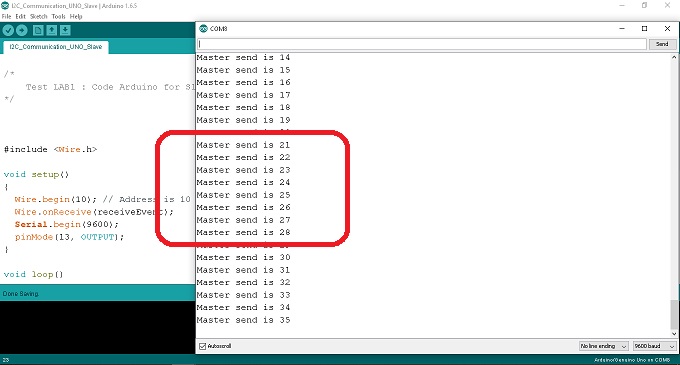
ในรูปที่ 4 การแสดงผลที่ได้เมื่อบอร์ด Arduino รับข้อมูลที่ได้จากบอร์ดส่ง (Master) จากในรูปกรอบสีแดงจะเห็นว่าในส่วนของข้อความ (Master send is) จะเป็นผลที่ได้จากการรับค่าตัวอักษรจากคำสั่ง char c = Wire.read(); และ Serial.print(c); จากนั้นที่ตำแหน่งตัวเลขจะเป็นผลที่ได้จากการรับค่าตัวแปร add จากคำสั่ง int add = Wire.read(); และ Serial.println(add);
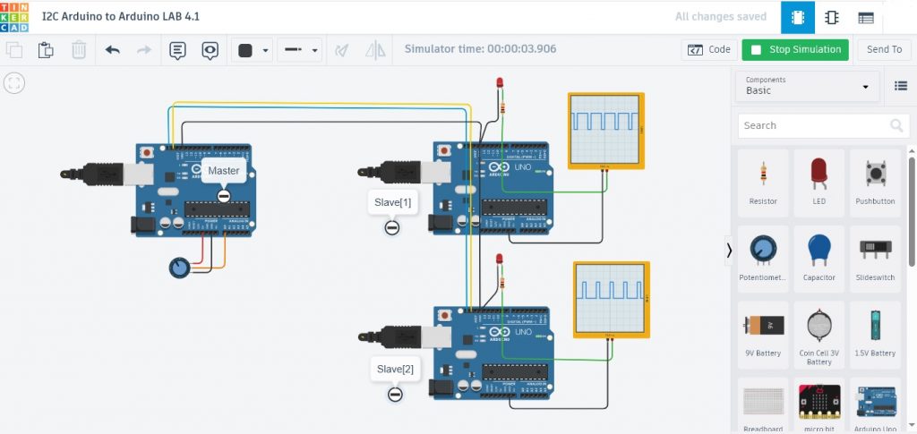
ในรูปที่ 5 เป็นการทดลองที่ 2 ด้วยการสื่อสารระหว่างบอร์ด Arduino UNO จำนวน 3 บอร์ด โดยบอร์ดที่ 1 จะทำหน้าที่ส่งของมูล (Master) ไปยังบอร์ด Arduino ที่ 2 (Slave[1]) และบอร์ด Arduino ที่ 3 (Slave[2]) ตามลำดับ โดยในการส่งจะระบุหมายเลขประจำตัวบอร์ดรับข้อมูลก่อน เพื่อให้การสื่อสารเป็นไปอย่างถูกต้อง
/*
    Test LAB2 : Code Arduino for Master
*/

#include <Wire.h>

void setup()
{
  Wire.begin();
}

byte add = 0;
byte Invadd = 0;

void loop()
{
  add++;
  Wire.beginTransmission(10);  // Address is 10 for Slave[1]
  Wire.write("Master send is ");
  Wire.write(add);
  Wire.endTransmission();

  Invadd = (255-add);
  Wire.beginTransmission(20);  // Address is 20 for Slave[2]
  Wire.write("Master send is ");
  Wire.write(Invadd);
  Wire.endTransmission();

  delay(10);
}
สำหรับโปรแกรมที่แสดงข้างบนนี้ Test LAB2 : Code Arduino for Master จะเป็นโปรแกรมสำหรับบอร์ด Arduino ที่ 1 (Master) โดยจะส่งตัวอักษร (Master send is) และข้อมูลค่าตัวแปร (add) ไปยังบอร์ด Arduino ที่ 2 (Slave[1] ตัวบนด้านซ้ายมือ Address is 10) และส่งตัวอักษร (Master send is) และข้อมูลค่าตัวแปร (Invadd) ไปยังบอร์ด Arduino ที่ 3 (Slave[2] ตัวล่าด้านซ้ายมือ Address is 20) ตามลำดับ
/*
    Test LAB2 : Code Arduino for Slave[1]
*/

#include <Wire.h>

void setup()
{
  Wire.begin(10); // Address is 10
  Wire.onReceive(receiveEvent);
  Serial.begin(9600);
  pinMode(9,OUTPUT);
  pinMode(13,OUTPUT);
}

void loop()
{
  digitalWrite(13, HIGH);
  delay(200);
  digitalWrite(13, LOW);
  delay(200);
}

void receiveEvent(int howMany)
{
  while(1 < Wire.available())
  {
    char c = Wire.read();
    Serial.print(c);                   // print the character
  }
    byte add = Wire.read();    // receive byte as an integer
    analogWrite(9,add);
    Serial.println(add);           // print the integer
}
โปรแกรมการทดลองข้างบน Test LAB2 : Code Arduino for Slave[1] จะทำหน้าที่รับค่าตัวอักษร (Master send is) และข้อมูลค่าตัวแปร (add) เท่านั้น ทั้งนี้เนื่องจากบอร์ดส่งข้อมูล (Master) จะระบุหมายเลข 10 (Address is 10) กำหนดไว้ จากนั้นนำข้อมูลที่ได้ไปแสดงผลและกำหนดขนาดสัญญาณพัลซ์วิดธ์มอดูเลตขั่นที่ขา D9 ด้วยคำสั่ง analogWrite(9,add);
/*
    Test LAB2 : Code Arduino for Slave[2]
*/

#include <Wire.h>

void setup()
{
  Wire.begin(20); // Address is 20
  Wire.onReceive(receiveEvent);
  Serial.begin(9600);
  pinMode(9,OUTPUT);
  pinMode(13,OUTPUT);
}

void loop()
{
  digitalWrite(13, HIGH);
  delay(500);
  digitalWrite(13, LOW);
  delay(500);
}

void receiveEvent(int howMany)
{
  while(1 < Wire.available())
  {
    char c = Wire.read();
    Serial.print(c);                    // print the character
  }
    byte add = Wire.read();    // receive byte as an integer
    analogWrite(9,add);
    Serial.println(add);           // print the integer
}
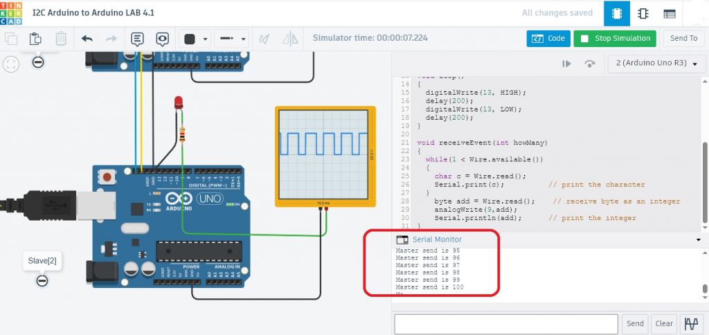
โปรแกรมการทดลองข้างบน Test LAB2 : Code Arduino for Slave[2] จะทำหน้าที่รับค่าตัวอักษร (Master send is) และข้อมูลค่าตัวแปร (add) เท่านั้น ทั้งนี้เนื่องจากบอร์ดส่งข้อมูล (Master) จะระบุหมายเลข 20 (Address is 20) กำหนดไว้ จากนั้นนำข้อมูลที่ได้ไปแสดงผลและกำหนดขนาดสัญญาณพัลซ์วิดธ์มอดูเลตขั่นที่ขา D9 ด้วยคำสั่ง analogWrite(9,add);
การทดลองสื่อสารแบบ I2C ในโครงงานนี้เป็นการทดลองอย่างง่าย เพื่อให้ผู้อ่านสามารถนำตัวอย่างไปใช้งานได้ง่ายและรวดเร็วขึ้น ทั้งนี้การใช้วิธีสื่อสารแบบนี้เป็นรูปแบบหนึ่งที่นิยมใช้งานมากในกลุ่มของอุปกรณ์ต่อร่วมกับบอร์ดควบคุมต่างๆ ในปัจจุบัน สำหรับในส่วนของการสื่อสารที่ซับซ้อนขึ้น อย่างการใช้โปรแกรมคำสั่งเพื่อใช้งานทั่วไปและการกำหนดค่าให้กับรูปแบบคำสั่ง (atomic states and bit operations) สามารถศึกษาเพิ่มเติมตามลิ้งก์เว็บไซต์อ้างอิงข้างล่างนี้ครับ.
Reference
- https://en.wikipedia.org/wiki/I%C2%B2C
- https://www.ti.com/lit/an/sbaa565/sbaa565.pdf
- https://learn.sparkfun.com/tutorials/i2c/all
- https://docs.arduino.cc/learn/communication/wire/
- https://www.robot-electronics.co.uk/i2c-tutorial
- https://deepbluembedded.com/i2c-communication-between-two-arduino/
- https://dronebotworkshop.com/i2c-arduino-arduino/
- https://www.instructables.com/I2C-between-Arduinos/
- https://microcontrollerslab.com/arduino-i2c-tutorial-communication-between-arduino-boards/
- https://www.tinkercad.com/
- https://fabacademy.org/2020/labs/akgec/students/afsha/week16.html