Wireless Control DC-DC Buck Converter Based on NodeMCU ESP32
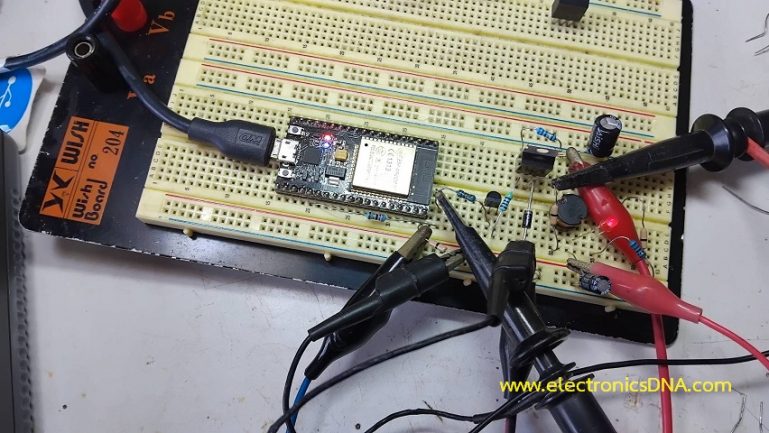
โครงงานนี้เป็นการทดลองใช้บอร์ดควบคุม NodeMCU ESP32 ควบคุมการทำงานของสวิตชิ่งโหมด ดีซี ทู ดีซี บักคอนเวอร์เตอร์ (DC to DC Buck Converter) แบบไร้สาย ด้วยโมดูลบูลทูธภายใน NodeMCU ESP32 และใช้โทรศัพท์มือถือที่ติดตั้งแอพพลิเคชั่น Serial Bluetooth Terminal ในการกำหนดค่าแรงดันเอาต์พุตที่ต้องการอย่างเช่น 3V, 6V และ 9V โดยโครงงานนี้จะเป็นไอเดียเบื้องต้น สำหรับนำไปพัฒนาโครงงานอื่นๆ ได้ตามต้องการ
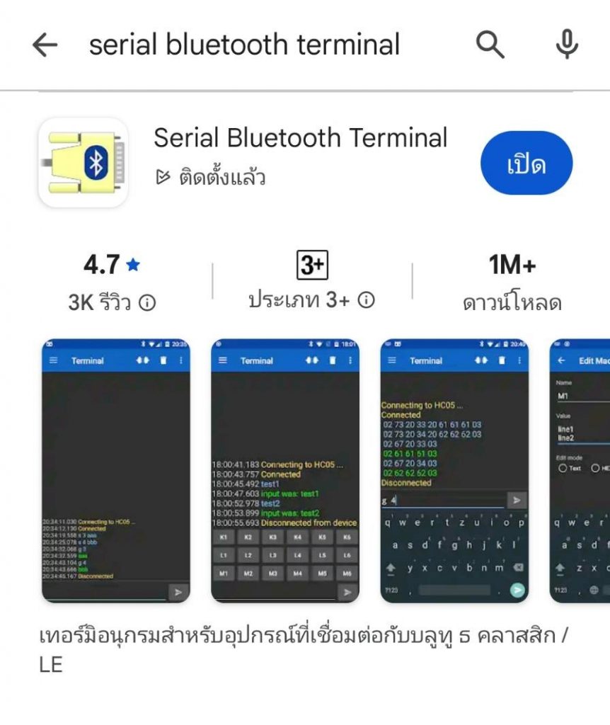
รูปที่ 1 ดาวน์โหลดแอพพลิเคชั่น Serial Bluetooth Terminal ใน Google Play store จากนั้นทำการติดตั้ง ซึ่งเมื่อเราติดตั้งเสร็จเรียบร้อยแล้ว ขั้นตอนต่อไปจะเป็นการเชื่อมต่อกับ NodeMCU ESP32 ในรูปที่ 2 ลักษณะของแอพพลิเคชั่น Serial Bluetooth Terminal ที่ติดตั้งเสร็จแล้ว
Arduino Library for BluetoothSerial.h
/*
  Arduino Code By : https://randomnerdtutorials.com/esp32-bluetooth-classic-arduino-ide/
*/

#include "BluetoothSerial.h"

#if !defined(CONFIG_BT_ENABLED) || !defined(CONFIG_BLUEDROID_ENABLED)
#error Bluetooth is not enabled! Please run `make menuconfig` to and enable it
#endif

BluetoothSerial SerialBT;

void setup() {
  Serial.begin(115200);
  SerialBT.begin("ESP32test"); // Bluetooth device name
  Serial.println("The device started, now you can pair it with bluetooth!");
}

void loop() {
  if (Serial.available()) {
    SerialBT.write(Serial.read());
  }
  if (SerialBT.available()) {
    Serial.write(SerialBT.read());
  }
  delay(20);
}
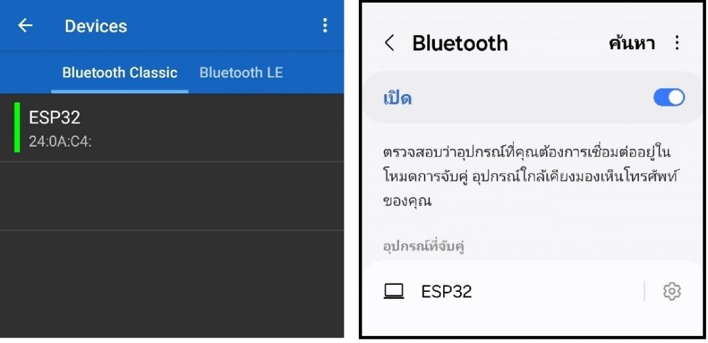
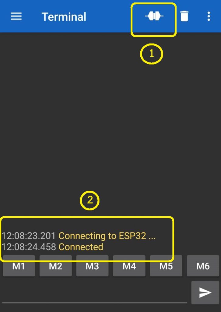
การทดลองที่ 1 เป็นการเชื่อมต่อระหว่าง NodeMCU ESP32 และ Serial Bluetooth Terminal ด้วยการใช้โปรแกรมคำสั่ง Arduino ที่แสดงข้างบน ดาวน์โหลดโปรแกรมไปยัง NodeMCU ESP32 โดยใช้ไลบารี BluetoothSerial.h จากนั้นให้เปิดแอพพลิเคชั่นและสังเกตข้อความแจ้งการเชื่อมต่อที่แสดงให้ทราบดังรูปที่ 3 และรูปที่ 4
จากนั้นทดลองการส่งข้อความเบื้องต้นระหว่าง NodeMCU ESP32 และแอพพลิเคชั่น Serial Bluetooth Terminal ด้วยการส่งข้อความ 1234 จากแอพพลิเคชั่น Serial Bluetooth Terminal ไปยังโปรแกรม Arduino IDE ที่เชื่อมต่อกับบอร์ด NodeMCU ESP32 อยู่ และจากนั้นทดลองส่งข้อความ 56789 จากโปรแกรม Arduino IDE กลับมายังแอพพลิเคชั่น Serial Bluetooth Terminal อีกครั้ง ผลการทดลองแสดงดังในรูปที่ 5 และรูปที่ 6
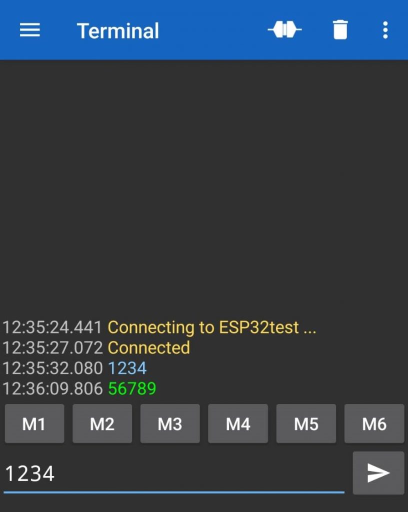
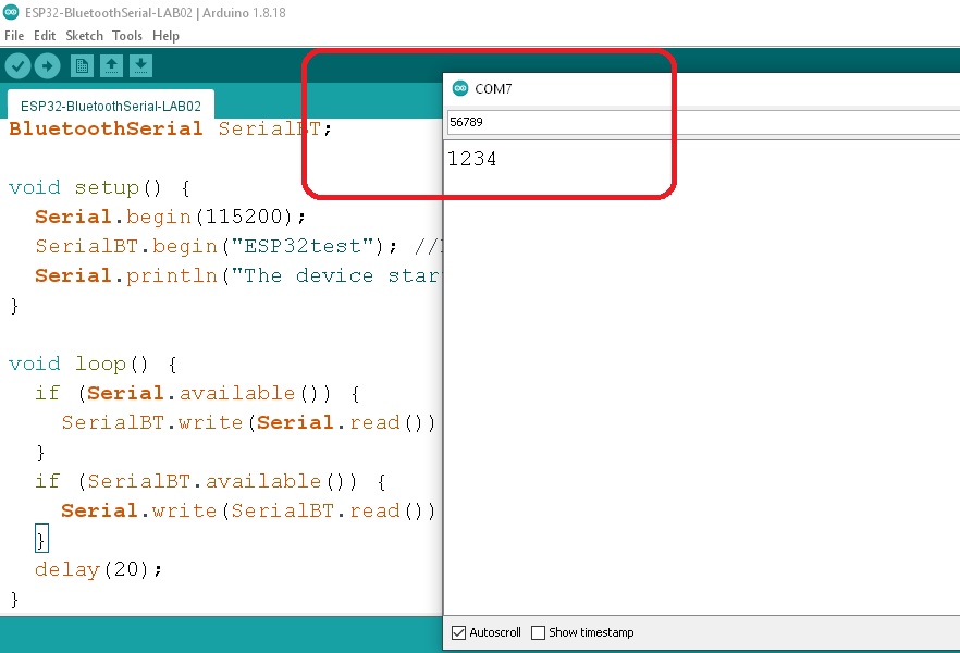
ในรูปที่ 5 ข้อความบนแอพพลิเคชั่น Serial Bluetooth Terminal โดยในตัวอย่างจะเป็นเลข 1234 เป็นข้อความสีฟ้า เพื่อให้ทราบว่าข้อความถูกส่งออกไปและจะแสดงที่โปรแกรม Arduino IDE ช่องรับข้อความในรูปที่ 6 เป็น 1234 เช่นกัน จากนั้นในโปรแกรม Arduino IDE จะส่งข้อความ 56789 ออกไป โดยแอพพลิเคชั่น Serial Bluetooth Terminal จะแสดงข้อความเป็นสีเขียวให้ทราบ
การทดลองที่ 2 เป็นการทดลองให้ NodeMCU ESP32 สร้างสัญญาณพัลซ์วิดธ์มอดูเลตชั่นออกมาที่ขา GPIO2 สำหรับควบคุมการทำงานของวงจรดีซี ทู ดีซี บักคอนเวอร์เตอร์ โดยโปรแกรมที่ใช้ในการทดลองที่ 2 ดังแสดงข้างล่าง
// Test PWM GPIO2 for NodeMCU ESP32

  const int PWMpin = 2;     // PWM to GPIO2
  const int freq = 35000;   // setting freq for PWM
  const int resolution = 8; // 0-255 Step

void setup(){
  ledcAttach(PWMpin, freq, resolution);
}

void loop(){
 ledcWrite(PWMpin,0);
 delay(1000);
 ledcWrite(PWMpin,64);
 delay(1000);
 ledcWrite(PWMpin,128);
 delay(1000);
 ledcWrite(PWMpin,192);
 delay(1000);
 ledcWrite(PWMpin,255);
 delay(1000);
}
สำหรับโปรแกรมการทดลองที่ 2 จะทดลองให้ NodeMCU ESP32 สร้างสัญญาณพัลซ์วิดธ์มอดูเลตชั่นออกมาที่ขา GPIO2 ด้วยคำสั่ง ledcAttach(PWMpin, freq, resolution); และ ledcAttach(PWMpin, freq, resolution); ซึ่งในการทดลองนี้จะให้ NodeMCU ESP32 ส่งสัญญาณที่มีค่าดิวตี้ไซเกิล 0%, 25%, 50%, 75% และ 100% ความถี่เท่ากับ 35kHz ตามลำดับ เพื่อให้สามารถนำโปรแกรมคำสั่งไปใช้งานในขั้นตอนต่อไป
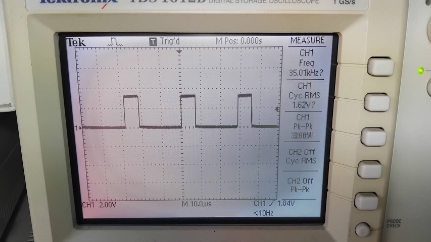
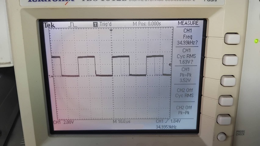
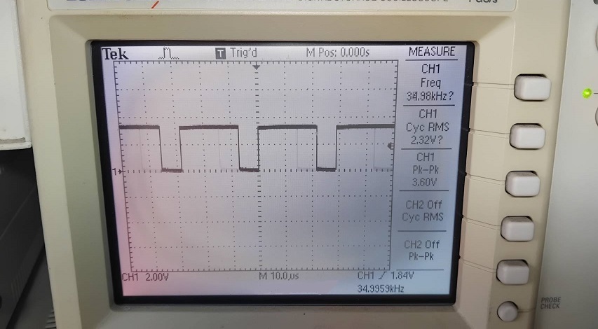
ในรูปที่ 7 ถึงรูปที่ 9 แสดงผลการทดลองที่ 2 บางส่วน จากโปรแกรมทดลองที่ 2 ด้วยการกำหนดให้ NodeMCU ESP32 ส่งสัญญาณพัลซ์วิดมอดูเลตชั่นที่ดิวตี้ไซเกิล 0%, 25%, 50%, 75% และ 100% ตามลำดับและความถี่เท่ากับ 35kHz
การทดลองที่ 3 จะเป็นการรวมโปรแกรมคำสั่งจากการทดลองที่ 1 และการทดลองที่ 2 เข้าด้วยกันเพื่อให้แอพพลิเคชั่น Serial Bluetooth Terminal สามารถส่งคำสั่งควบคุมมายัง NodeMCU ESP32 จากนั้นตัว NodeMCU ESP32 จะส่งสัญญาณพัลซ์วิดมอดูเลตชั่นสำหรับควบคุมวงจรดีซี ทู ดีซี บักคอนเวอร์เตอร์ต่อไป และโปรแกรมที่ใช้ในการทดลองที่ 3 ดังแสดงข้างล่าง
/*
  Arduino Code By : https://randomnerdtutorials.com/esp32-bluetooth-classic-arduino-ide/
*/

// Load libraries
#include "BluetoothSerial.h"

// Check if Bluetooth configs are enabled
#if !defined(CONFIG_BT_ENABLED) || !defined(CONFIG_BLUEDROID_ENABLED)
#error Bluetooth is not enabled! Please run `make menuconfig` to and enable it
#endif

// Bluetooth Serial object
BluetoothSerial SerialBT;

// GPIO where LED is connected to
const int ledPin =  2;      // GPIO2
const int freq = 35000;     // setting PWM properties
const int resolution = 8;   // 0-255 Step

// Handle received and sent messages
String message = "";
char incomingChar;

// Timer: auxiliar variables
unsigned long previousMillis = 0;    // Stores last time temperature was published
const long interval = 1000;          // interval at which to publish sensor readings

void setup() {
  pinMode(ledPin, OUTPUT);
  ledcAttach(ledPin, freq, resolution);
 // analogReadResolution(12);
  Serial.begin(115200);

  SerialBT.begin("ESP32 Control DC-DC Converter");  // Bluetooth device name
  Serial.println("The device started, now you can pair it with bluetooth!");
  SerialBT.println("ESP32 Control DC-DC Converter");   // Sense Text for Application
}

void loop() {

  // Read received messages (LED control command)
  if (SerialBT.available()){
    char incomingChar = SerialBT.read();
    if (incomingChar != '\n'){
      message += String(incomingChar);
    }
    else{
      message = "";
    }
    Serial.write(incomingChar);
  }
  // Check received message and control output accordingly
  if (message =="PWM3V"){
     ledcWrite(ledPin, 64);
     SerialBT.println("OK PWM for 3V");   // Sense Text for Application
  }
  else if (message =="PWM6V"){
     ledcWrite(ledPin, 128);
     SerialBT.println("OK PWM for 6V");   // Sense Text for Application
  }
  else if (message =="PWM9V"){
     ledcWrite(ledPin, 192);
     SerialBT.println("OK PWM for 9V");   // Sense Text for Application
  }
   else if (message =="PWM0V"){
     ledcWrite(ledPin, 0);
     SerialBT.println("OK PWM for 0V");   // Sense Text for Application
  }

  delay(10);
}
สำหรับโปรแกรมการทดลองที่ 3 เป็นการรับค่าที่ส่งมาจากแอพพลิเคชั่น Serial Bluetooth Terminal เข้ามายังตัวแปร message จากนั้นนำจะนำมาเปรียบเทียบ if (message ==”PWMxV”) กับ PWM3V, PWM6V, PWM9V และ PWM0V เพื่อกำหนดขนาดของสัญญาณพัลซ์วิดมอดูเลตชั่น ledcWrite(ledPin, x); ในการควบคุมวงจรดีซี ทู ดีซี บักคอนเวอร์เตอร์
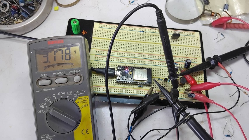
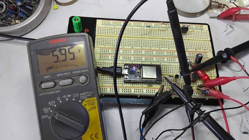
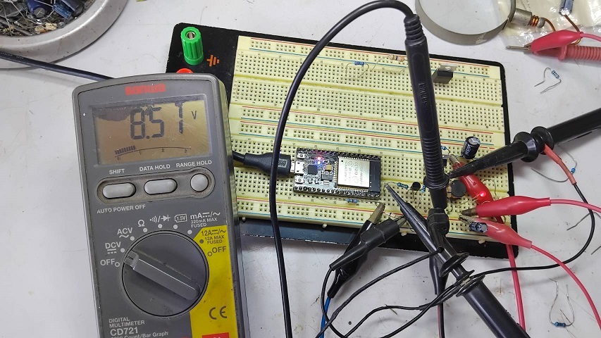
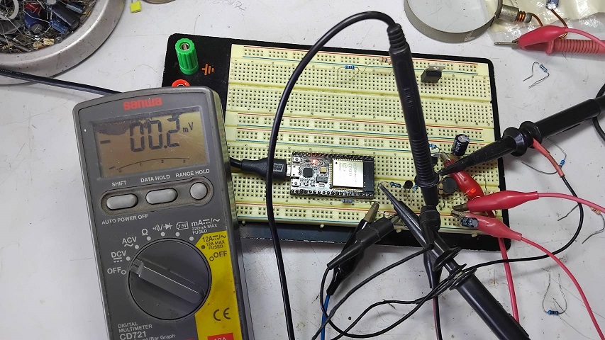
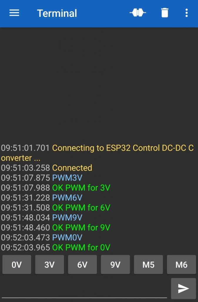
รูปที่ 10 ถึงรูปที่ 14 แสดงผลการทดลองที่ 3 เมื่อกำหนดให้ NodeMCU ESP32 รับค่าจากแอพลิเคชั่น Serial Bluetooth Terminal จากนั้นส่งสัญญาณพัลซ์วิดมอดูเลตชั่นควบคุมวงจรดีซี ทู ดีซี บักคอนเวอร์เตอร์ ให้แรงดันเอาต์พุตมีค่าเท่ากับ 3V, 6V, 9V และ 0V ตามลำดับ โดยในการทดลองจะให้ค่าใกล้เคียงตามที่กำหนดเนื่องจากเป็นการควบคุมแรงดันเอาต์พุตแบบเปิด (Open Loop Control) ในรูปที่ 14 จะเป็นการส่งคำสั่งจากแอพลิเคชั่นไปยัง NodeMCU ESP32 (ตัวหนังสือสีฟ้า) และจากนั้น NodeMCU ESP32 จะส่งข้อความกลับมายังแอพลิเคชั่น (ตัวหนังสือสีเขียว) ให้ทราบผลการทำงาน
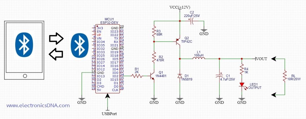
สำหรับการควบคุมด้วย NodeMCU ESP32 แบบไร้สาย โดยทั่วไปสามารถควบคุมได้ทั้งผ่านโมดูลบูลทูธ (Bluetooth) และไวไฟ (WiFi) ซึ่งผู้ใช้งานสามารถเลือกได้ตามต้องการ ทั้งนี้ควบคุมบอร์ด NodeMCU ESP32 จะมีโมดูลโมดูลบูลทูธและไวไฟให้ใช้งานทั้ง 2 แบบ สำหรับโครงงานนี้เป็นการนำมาประยุกต์ใช้ในการควบคุมวงจรดีซี ทู ดีซี บักคอนเวอร์เตอร์ผ่านโมดูลบูลทูธและใช้แอพพลิเคชั่นบนโทรศัพท์มือถือในการควบคุมค่าแรงดันเอาต์พุตตามที่ต้องการ
Reference
- https://randomnerdtutorials.com/esp32-pwm-arduino-ide/
- https://deepbluembedded.com/esp32-pwm-tutorial-examples-analogwrite-arduino/
- https://deepbluembedded.com/esp32-dac-audio-arduino-examples/
- https://www.espressif.com/sites/default/files/documentation/esp32_datasheet_en.pdf
- https://www.espressif.com/sites/default/files/documentation/esp32-wroom-32_datasheet_en.pdf
- https://forum.arduino.cc/t/pwm-on-esp32-not-working/1137083
- https://docs.espressif.com/projects/esp-idf/en/stable/esp32/api-reference/peripherals/ledc.html