Getting Started STM32F103C Board with Arduino IDE [EP3]
ในตอนที่ 3 นี้จะเป็นการทดลองใช้งานบอร์ดควบคุม STM32F103C8T6 กันต่อ เกี่ยวกับการสร้างสัญญาณพัลซ์วิดมอดูเลตชั่น (PWM), การทดลองการอินเตอร์รัพท์จากสัญญาณภายนอก, การใช้งานอินเตอร์รัพท์ไทร์เมอร์ภายใน สำหรับเป็นการเรียนรู้การใช้งานฟังก์ชันต่างๆ ของชิฟ STM32F103C8T6 เพิ่มเติมกันต่อไป
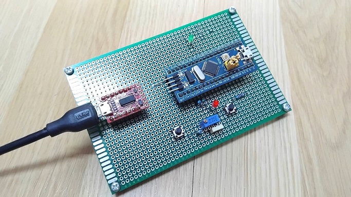
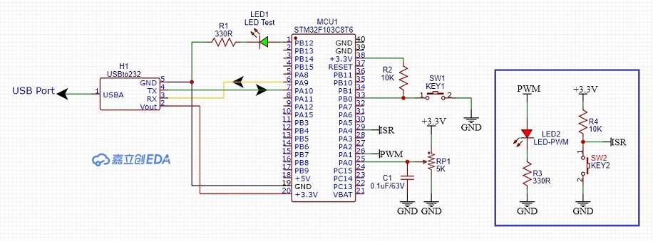
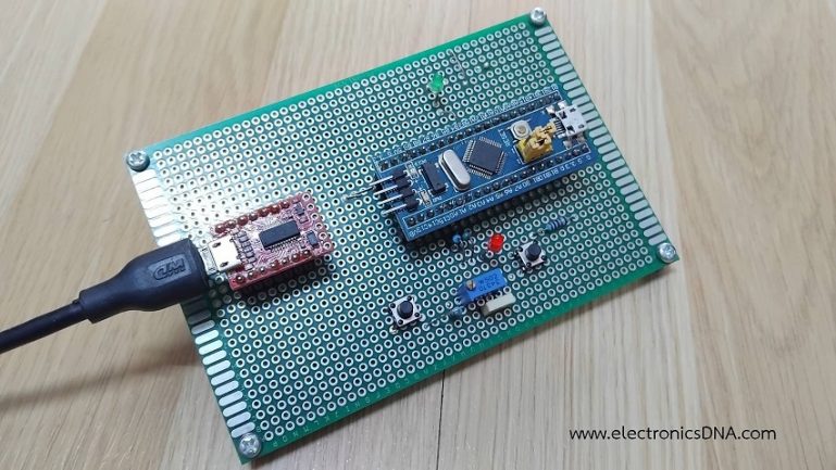
รูปที่ 1 แสดงการต่ออุปกรณ์ต่างๆ สำหรับทดลองการทำงานให้กับบอร์ดควบคุม STM32F103C8T6 บอร์ดทดลองและการต่ออุปกรณ์เพิ่มคือ แอลอีดี (LED2) ที่ตำแหน่งขา PA1 (เป็นขาส่งสัญญาณพัลซ์วิดมอดูเลตชั่นได้) เพื่อสังเกตความสว่างที่ตัวแอลอีดี และที่ตำแหน่งขา PA4 สำหรับการอินเตอร์รัพท์จากสัญญาณภายนอก (ISR) โดยผลการทดลองจะแสดงที่หน้าต่าง Serial Monitor เป็นหลักสำหรับการทดลอง 3 แบบ เพื่อให้เข้าใจง่ายขึ้น
/* Lesson 4: Analog Read and PWM Write */

const int potPin = PA0;  // ADC Pin
const int ledPin = PA1;  // PWM Pin

void setup() {
  pinMode(ledPin, OUTPUT);
  Serial.begin(9600);
  // No pinMode needed for analogRead
}

void loop() {
  int sensorValue = analogRead(potPin); // Reads 0 - 4095

  // STM32 PWM default resolution is usually 8-bit (0-255) in Arduino API
  // We must map the 12-bit input to 8-bit output
  int pwmValue = map(sensorValue, 0, 4095, 0, 255);

  Serial.print(" PWM = ");
  Serial.println(pwmValue);
  analogWrite(ledPin, pwmValue);
  delay(100);
}
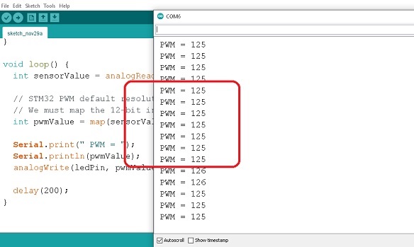
การทดลองที่ 4 ต่อจากเนื้อหาตอนที่ 2 เป็นการสร้างสัญญาณพัลซ์วิดมอดูเลตชั่น (PWM) ที่ตำแหน่งขา PA1 ด้วยการรับค่าสัญญาณอะนาลอกจากตำแหน่งขา PA0 เพื่อปรับความกว้างสัญญาณพัลซ์วิดมอดูเลตชั่นที่ต้องการ ในรูปที่ 3 แสดงข้อมูลสำหรับกำหนค่าสัญญาณพัลซ์วิดมอดูเลตชั่นที่ได้ (PWM = 125) ที่ตำแหน่งขา PA1 เมื่อปรับค่าแรงดันสัญญาณอะนาลอกที่ขา PA0 และการแสดงค่าที่หน้าต่าง Serial Monitor
/* Lesson 5: External Interrupt */

const int buttonPin = PA4;   // Pin External Interrupt
const int ledPin = PB12;
volatile bool ledState = false;  // 'volatile' is required for ISR variables

void setup() {
  Serial.begin(9600);
  pinMode(ledPin, OUTPUT);
  pinMode(buttonPin, INPUT_PULLUP);

  // Attach interrupt: specific syntax for STM32
  attachInterrupt(digitalPinToInterrupt(buttonPin), toggleLED, FALLING);
}

void loop() {
  // Main loop can do heavy calculations here
  // The button will work regardless
  delay(1000);
}

// This function runs automatically when button is pressed
void toggleLED() {
  Serial.println(" Active Interrupt");
  ledState = !ledState;
  digitalWrite(ledPin, ledState ? LOW : HIGH);
}
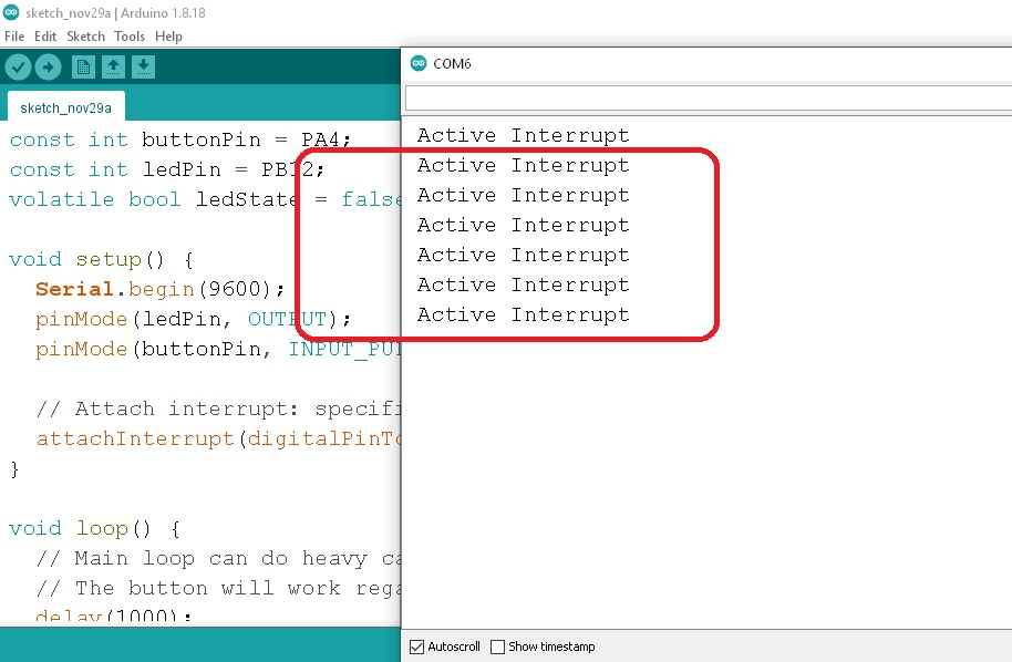
การทดลองที่ 5 เป็นการรับสัญญาณอินเตอร์รัพท์จากภายนอก (External Interrupt) เข้ามายังขา PA4 ด้วยการต่อสวิตช์ จากนั้นจะกำหนดให้แอลอีดีที่ขา PB12 ติดสว่างขึ้นและดับลงสลับกันให้ทราบเมื่อมีการกดสวิตช์ ในรูปที่ 4 แสดงข้อความการทำงานเมื่อเกิดอินเตอร์รัพท์ขึ้นที่หน้าต่าง Serial Monitor ทั้งนี้การใช้งานอินเตอร์รัพท์สำหรับการควบคุมด้วยไมโครคอนโทรลเลอร์ต่างๆ จะมีประโยชน์มากเมื่อนำไปใช้พัฒนาโครงงานต่างๆ
 /*
 Lesson 6 :  Timer Interrupt
 Credit By Bryan Newbold for LeafLabs
 */

const int ledPin = PB12;
const int buttonPin = PA4;
#define LED_RATE 500000  // in microseconds; should give 0.5Hz toggles

void handler_led(void);
int toggle = 0;

void setup()
{
	Serial.begin(9600);
    // Set up the LED to blink
    pinMode(ledPin, OUTPUT);

    // Setup LED Timer
    Timer2.setMode(TIMER_CH1, TIMER_OUTPUTCOMPARE);
    Timer2.setPeriod(LED_RATE);   // in microseconds
    Timer2.setCompare(TIMER_CH1, 1);      // overflow might be small
    Timer2.attachInterrupt(TIMER_CH1, handler_led);
}

void loop() {
     delay(1000);
}

void handler_led(void) {

    Serial.println(" Timer2 for Active LED PB12");
    toggle ^= 1;
    digitalWrite(ledPin, toggle);
}
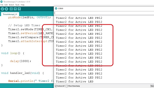
การทดลองที่ 6 เป็นการทดลองการใช้งานอินเตอร์รัพท์ภายในจากไทร์เมอร์ (Timer Interrupt) สำหรับบอร์ด STM32F103C8T6 ด้วยการให้แอลอีดีที่ขา PB12 กระพริบด้วยฟังก์ชั่น void handler_led(void) เท่ากับ 0.5 วินาทีตลอดเวลา โดยใช้โปรแกรม Lesson 6 : Timer Interrupt ผลการทดลองดังแสดงในรูปที่ 5 ซึ่งแสดงในหน้าต่าง Serial Monitor ของโปรแกรม Arduino IDE ในตอนต่อไปจะเป็นการสร้างสัญญาณพัลซ์วิดมอดูเลตชั่นความถี่สูงในรูปแบบต่างๆ สำหรับนำไปประยุกต์ใช้งานกับแหล่งจ่ายไฟเลี้ยงแบบสวิตชิ่งเพาวเวอร์ซัพพลาย (SMPSU), ดีซี ทู ดีซี คอนเวอร์เตอร์ (DC to DC Converter) และวงจรอินเวอร์เตอร์ (Inverter) เป็นต้น
Reference
- https://www.st.com/en/microcontrollers-microprocessors/stm32f103.html
- https://www.st.com/resource/en/datasheet/stm32f103c8.pdf
- https://github.com/stm32duino/BoardManagerFiles/raw/master/STM32/package_stm_index.json
- https://www.pcb-hero.com/blogs/lickys-column/stm32f103c8t6-blue-pill-development-board
- https://forum.arduino.cc/t/wiring-uart-communication-between-arduino-nano-softserial-and-stm32f103c8t6/638799/2
- https://reversepcb.com/stm32f103c8t6/
- https://www.instructables.com/How-to-Program-STM32F103C8T6-With-ArduinoIDE/