Arduino to Arduino by using SPI Communication
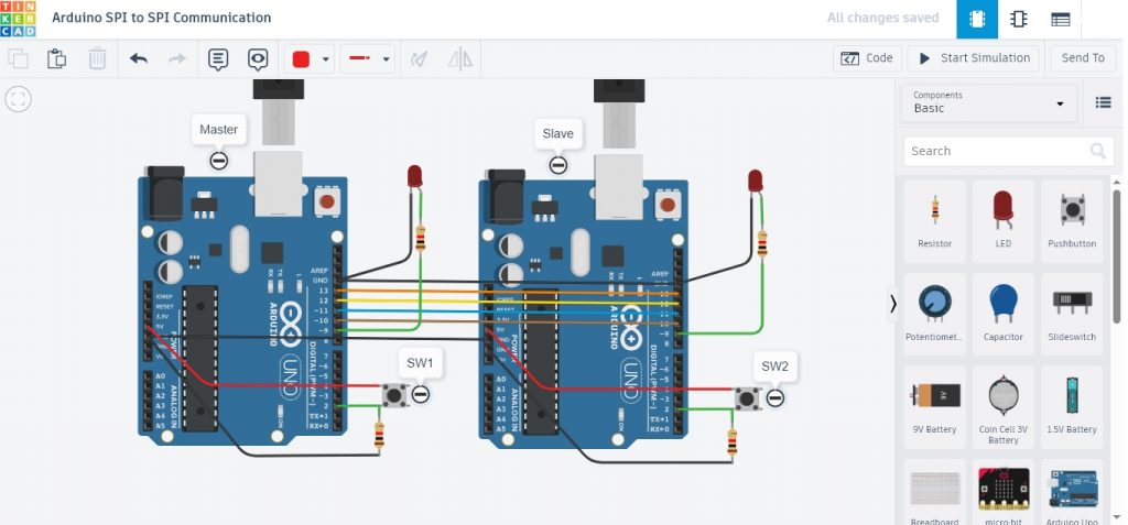
โครงงานนี้เป็นการทดลองการสื่อสารแบบ SPI (Serial Peripheral Interface) ระหว่างบอร์ดควบคุม Arduino ด้วยการส่งตัวอักษร (Character) ระหว่างบอร์ด Arduino ตัวที่ 1 (Master) ไปยังบอร์ด Arduino ตัวที่ 2 (Slave) ในการทดลองที่ 1 และการทดลองที่ 2 จะเป็นการทดลองให้บอร์ด Arduino ทั้ง 2 ส่งข้อมูลระหว่างกันและสามารถควบคุมการเปิดและปิดแอลอีดีได้ ทั้งนี้เพื่อศึกษารูปแบบการต่อวงจรและการใช้โปรแกรมคำสั่งในการสื่อสารแบบ SPI และเป็นไอเดียของการนำไปประยุกต์ใช้งานต่างๆ ต่อไป

// https://www.makerguides.com/master-slave-spi-communication-arduino/
// Arduino Master board [Lab1]

#include "SPI.h"

char str[] = "Arduino Master\n";

void setup() {
  Serial.begin(115200);  // set baud rate to 115200 for usart
  SPI.begin();
  SPI.setClockDivider(SPI_CLOCK_DIV8);  //divide the clock by 8
  Serial.println("Arduino Master");
}

void loop(void) {
  digitalWrite(SS, LOW);  // enable Slave Select
  // send test string
  for (int i = 0; i < sizeof(str); i++)
    SPI.transfer(str[i]);
  digitalWrite(SS, HIGH);  // disable Slave Select
  delay(1000);
}
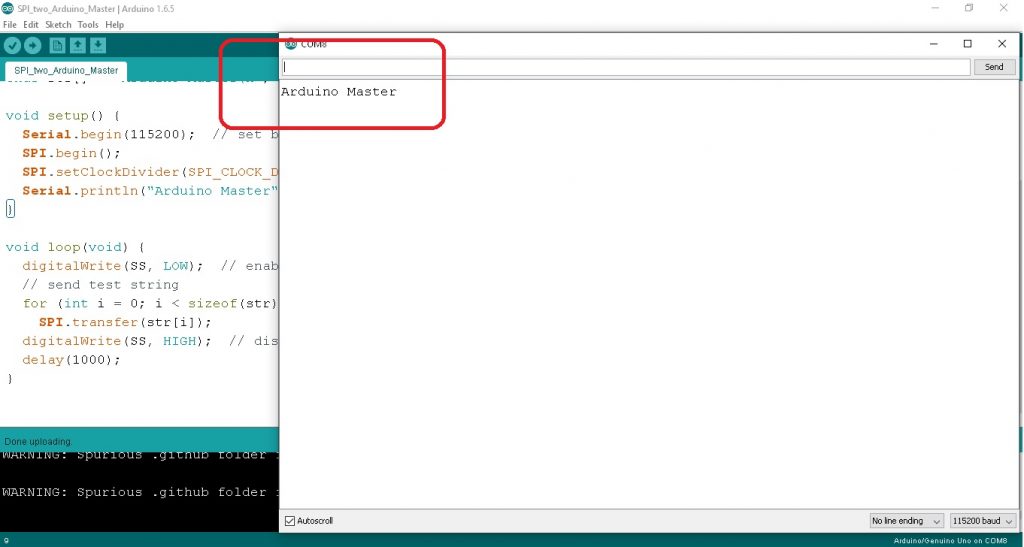
ในรูปที่ 3 และโปรแกรมการทดลอง Arduino Master board เป็นการส่งข้อความจากบอร์ด Master ด้วยข้อความ Arduino Master ไปยังบอร์ดรับ (Slave) ด้วยการเก็บตับอักษรไว้ที่คำสั่ง char str[] = “Arduino Master\n”; จากนั้นจะใช้คำสั่ง for (int i = 0; i < sizeof(str); i++) และ SPI.transfer(str[i]); ในการส่งตัวอักษรออกไป
// https://www.makerguides.com/master-slave-spi-communication-arduino/
// Arduino Slave board [Lab1]

#include "SPI.h"

char str[50];
volatile byte i;
volatile bool pin;

void setup() {
  Serial.begin(115200);  // set baud rate to 115200 for usart
  Serial.println("Arduino SLAVE");
  pinMode(MISO, OUTPUT);  // have to send on Master in so it set as output
  SPCR |= _BV(SPE);       // turn on SPI in slave mode
  i = 0;                  // buffer empty
  pin = false;
  SPI.attachInterrupt();  // turn on interrupt
}

void loop() {
  static int count;
  if (pin) {
    pin = false;  //reset the pin
    if (count++ < 5) {
      Serial.print(count);
      Serial.print(" : ");

      Serial.print(str);  //print the array on serial monitor
      if (count == 5) {
        delay(1000);
        Serial.println("The end data");
      }
      delay(1000);
      i = 0;  //reset button to zero
    }
  }
}

// Interrupt function
ISR(SPI_STC_vect) {
  char c = SPDR;  // read byte from SPI Data Register
  if (i < sizeof(str)) {
    str[i++] = c;                                   // save data in the next index in the array buff
    if ((c == '\r') || (c == '\n') || (c == '\0'))  //check for the end of the word
      pin = true;
  }
}
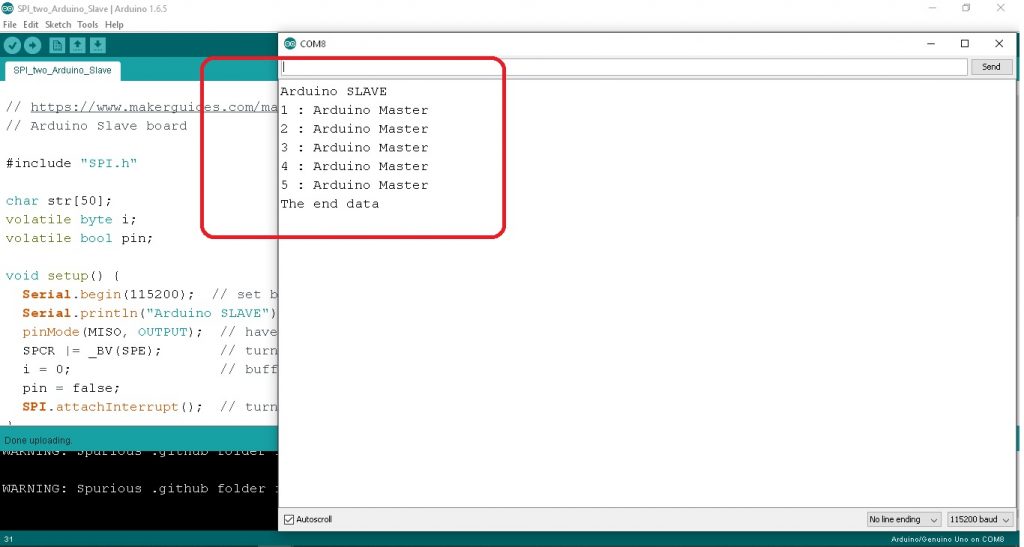
ในรูปที่ 4 และโปรแกรมทดลอง Arduino Slave board จะทำหน้าที่รับตัวอักษรเข้ามาที่คำสั่ง str[i++] = c; ที่อยู่ในฟังก์ชั่นอินเตอร์รัพท์ ISR(SPI_STC_vect) จากนั้นก็จะนำอักษรที่ได้ไปแสดงผลด้วยคำสั่ง Serial.print(str); เป็นจำนวน 5 ครั้ง และเมื่อครบ 5 ครั้งแล้วให้แสดงข้อความ The end data ให้ทราบ ซึ่งหมายความว่าบอร์ดควบคุม Arduino ทั้งสองสามารถสื่อสารกันได้ถูกต้อง
// https://microcontrollerslab.com/spi-communication-between-two-arduino-boards/
// Arduino Master board  [Lab2]

#include<SPI.h>
#define SW1 2
#define LED 9

int x;
int value;
void setup (void)

{
  Serial.begin(115200);
  pinMode(SW1,INPUT);
  pinMode(LED,OUTPUT);

  SPI.begin();
  SPI.setClockDivider(SPI_CLOCK_DIV8);
  digitalWrite(SS,HIGH);
}

void loop(void)
{
  byte m_send,m_receive;
  value = digitalRead(SW1);

  if(value == HIGH)
  {
    x = 1;
  }
  else
  {
    x = 0;
  }
  digitalWrite(SS, LOW);

  m_send = x;
  m_receive=SPI.transfer(m_send);

  if(m_receive == 1)
  {
   digitalWrite(LED,HIGH);
  }
  else
  {
   digitalWrite(LED,LOW);
  }
  delay(500);
}
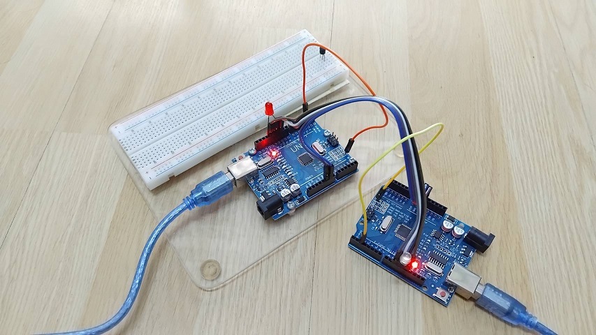
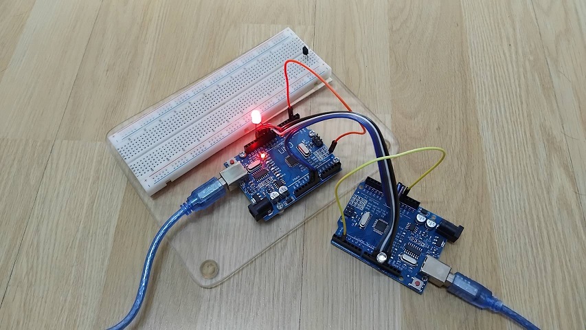
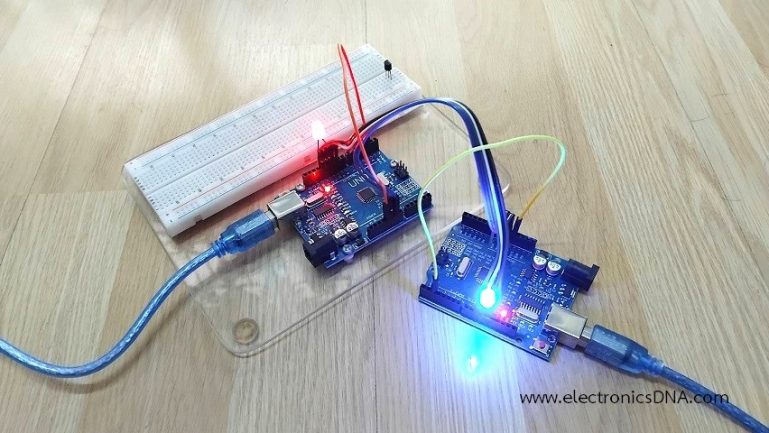
สำหรับรูปที่ 5 และรูปที่ 6 แสดงผลการทดลองที่เกิดขึ้นเมื่อโปรแกรมคำสั่งให้กับบอร์ด Arduino ทั้ง 2 บอร์ดแล้ว [Lab2] โดยในรูปที่ 5 จะเป็นการทดลองให้ขาอินพุต D2 ของบอร์ด Master และ Slave เป็นลอจิก 0 ทั้งคู่ (บอร์ดซ้ายมือคือ Slave และบอร์ดขวามือ Master) จะทำให้แอลอีดีดับทั้งคู่ จากนั้นในรูปที่ 6 กำหนดให้ขาอินพุต D2 ของบอร์ด Master เป็นลอจิก 1 และ Slave เป็นลอจิก 0 จะสังเกตเห็นว่าแอลอีดีที่บอร์ด Slave สีแดงจะติดสว่างขึ้น
// https://microcontrollerslab.com/spi-communication-between-two-arduino-boards/
// Arduino Slave board  [Lab2]

#include<SPI.h>
#define SW2 2
#define outputLED 9

volatile boolean received;
volatile byte Slavereceived,Slavesend;
int buttonvalue;
int x;

void setup()

{
  Serial.begin(115200);
  pinMode(SW2,INPUT);
  pinMode(outputLED,OUTPUT);
  pinMode(MISO,OUTPUT);

  SPCR |= _BV(SPE);
  received = false;

  SPI.attachInterrupt();

}

ISR (SPI_STC_vect)
{
  Slavereceived = SPDR;
  received = true;
}

void loop()
{
 if(received)
   {
      if (Slavereceived==1)
      {
        digitalWrite(outputLED,HIGH);
      }else
      {
        digitalWrite(outputLED,LOW);
      }

      buttonvalue = digitalRead(SW2);

      if (buttonvalue == HIGH)
      {
        x=1;

      }else
      {
        x=0;
      }

  Slavesend=x;
  SPDR = Slavesend;
  delay(500);
}
}
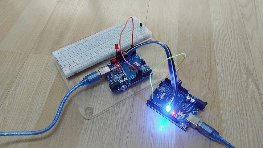
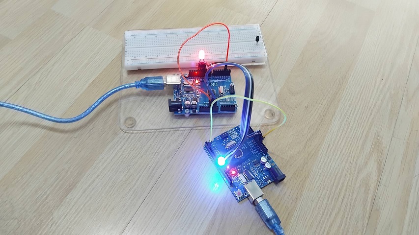
ในรูปที่ 7 เป็นการกำหนดให้ขาอินพุต D2 ของบอร์ด Master เป็นลอจิก 0 และ Slave เป็นลอจิก 1 จะสังเกตเห็นว่าแอลอีดีที่บอร์ด Master สีน้ำเงินจะติดสว่างขึ้น ส่วนในรูปที่ 8 จะเป็นการทดลองให้ขาอินพุต D2 ของบอร์ด Master และ Slave เป็นลอจิก 1 ทั้งคู่ จะสังเกตเห็นว่าแอลอีดีที่บอร์ด Slave และ Master สีแดงและสีน้ำเงินจะติดสว่างขึ้นนั้นเอง และสำหรับการทดลองในโครงงานทั้ง 2 แบบนี้ คงจะเป็นแนวความคิดเบื้องต้นให้ผู้อ่านสามารถนำไปประยุกใช้งานต่างๆ ต่อไปครับ
Reference
- https://en.wikipedia.org/wiki/Serial_Peripheral_Interface
- https://arduino.stackexchange.com/questions/16348/how-do-you-use-spi-on-an-arduino
- https://microcontrollerslab.com/spi-communication-between-two-arduino-boards/
- https://www.electronicwings.com/nodemcu/nodemcu-spi-with-arduino-ide
- https://www.makerguides.com/master-slave-spi-communication-arduino/
- https://iot-guider.com/arduino/using-serial-peripheral-interface-spi-in-arduino/
- https://www.analog.com/en/resources/analog-dialogue/articles/introduction-to-spi-interface.html