Arduino Based FOC Controller Two-Phase Bipolar Stepper Motor with IC L293D [EP1]
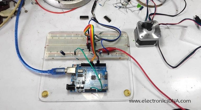
การควบคุมมอเตอร์ด้วยระบบ Field-Oriented Control (FOC) หรือเรียกว่า การควบคุมแบบเน้นสนามแม่เหล็ก เป็นการควบคุมในกลุ่มของการควบคุมแบบเวกเตอร์ (Vector control) โดยทั่วไปจำเป็นต้องมีการป้อนกลับตำแหน่งของโรเตอร์อย่างต่อเนื่อง (ผ่านทาง Absolute Encoder) เพื่อแปลงค่ากระแสไฟฟ้าระหว่างระบบพิกัดอ้างอิงแบบอยู่กับที่ (α,β) และแบบหมุน (d,q) โดยใช้วงจรขับแบบ Dual H-bridge ด้วยไอซี L293D โดยไม่ใช้ตัวเข้ารหัส (Encoder) วิธีการมาตรฐานที่ใช้คือ Open-Loop FOC (Sine-Cosine Vector Control) แทนที่จะใช้การขับเคลื่อนแบบ Full-step หรือ Half-step แบบแยกเป็นจังหวะ เราจะป้อนสัญญาณ PWM รูปคลื่นไซน์ที่ต่อเนื่องและมีเฟสต่างกัน 90 องศา (quadrature) เข้าสู่ขดลวดมอเตอร์โดยตรง ซึ่งช่วยให้เกิดการหมุนของสนามแม่เหล็กที่ราบรื่นและมีการสั่นสะเทือนน้อยที่สุด
หลักการทางคณิตศาสตร์เบื้องต้น
สำหรับสเต็ปเปอร์มอเตอร์แบบไบโพลาร์ 2 เฟส (Two-Phase bipolar) แรงดันไฟฟ้าของทั้งสองเฟสที่ตั้งฉากกัน คือ VA และ VB จะถูกคำนวณโดยขึ้นอยู่กับมุมทางไฟฟ้า θ ดังนี้คือ
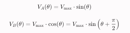
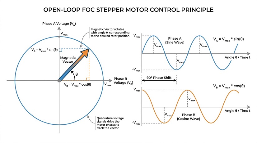
การใช้ตารางจำนวนสำหรับสร้างสัญญาณรูปไซน์ (sine lookup table) ขนาด 256 จำนวน จะช่วยให้เราหลีกเลี่ยงการคำนวณฟังก์ชันตรีโกณมิติด้วยเลขทศนิยม (floating-point) ซึ่งจะทำให้ไมโครคอนโทรลเลอร์ใช้ทรัพยากรสูงภายในลูปการทำงานหลัก
// -----------------------------------------------
// Open-Loop Stepper FOC Controller (No Libraries)
// Controls a 2-Phase Bipolar Stepper Motor using Sinusoidal PWM Vectors
// -----------------------------------------------

// Pin Definitions (Must support PWM)
const int PIN_A_POS = 5;  // Phase A+
const int PIN_A_NEG = 6;  // Phase A-
const int PIN_B_POS = 9;  // Phase B+
const int PIN_B_NEG = 10; // Phase B-

// Sine Look-Up Table (256 entries for high resolution smooth rotation)
// Maps 0 to 360 degrees electrical angle to a 0-255 PWM duty cycle
const uint8_t SINE_LUT[256] = {
  128, 131, 134, 137, 140, 143, 146, 149, 152, 155, 158, 162, 165, 168, 171, 174,
  177, 180, 183, 186, 189, 192, 195, 198, 201, 204, 207, 210, 212, 215, 218, 221,
  223, 226, 228, 231, 233, 236, 238, 240, 242, 244, 246, 247, 249, 251, 252, 253,
  254, 255, 255, 255, 255, 255, 254, 253, 252, 251, 249, 247, 246, 244, 242, 240,
  238, 236, 233, 231, 228, 226, 223, 221, 218, 215, 212, 210, 207, 204, 201, 198,
  195, 192, 189, 186, 183, 180, 177, 174, 171, 168, 165, 162, 158, 155, 152, 149,
  146, 143, 140, 137, 134, 131, 128, 125, 122, 119, 116, 113, 110, 107, 104, 101,
  98,  94,  91,  88,  85,  82,  79,  76,  73,  70,  67,  64,  61,  58,  55,  52,
  49,  46,  44,  41,  38,  35,  33,  30,  28,  25,  23,  20,  18,  16,  14,  12,
  11,  9,   7,   5,   4,   3,   2,   1,   1,   0,   1,   1,   2,   3,   4,   5,
  7,   9,   11,  12,  14,  16,  18,  20,  23,  25,  28,  30,  33,  35,  38,  41,
  44,  46,  49,  52,  55,  58,  61,  64,  67,  70,  73,  76,  79,  82,  85,  88,
  91,  94,  98,  101, 104, 107, 110, 113, 116, 119, 122, 125
};

// Global Variables
uint8_t electrical_angle = 0; // 0 to 255 maps to 0 to 360 electrical degrees
int target_speed = 100;  // 50-1000   Delay between electrical increments in microseconds (lower = faster)
int max_power = 128;     // 50-255    Voltage amplitude scale (0-255)

// Function Declarations
void setFOCVector(uint8_t angle, uint8_t power);

void setup() {

  Serial.begin(9600);
  pinMode(PIN_A_POS, OUTPUT);
  pinMode(PIN_A_NEG, OUTPUT);
  pinMode(PIN_B_POS, OUTPUT);
  pinMode(PIN_B_NEG, OUTPUT);

  // Set Timer 1 & Timer 2 to fast PWM (~31.2kHz) for noiseless operation
  TCCR1B = (TCCR1B & 0xF8) | 0x01;
  TCCR2B = (TCCR2B & 0xF8) | 0x01;
}

void loop() {
  // Step forward by updating the electrical vector angle
  electrical_angle++;

  // Apply sinusoidal voltage vector to Phase A and Phase B
  setFOCVector(electrical_angle, max_power);

  // Speed control delay
  delayMicroseconds(target_speed);
}

// -------------------------------------------------------------------------
// Core FOC Math: Converts Electrical Angle to Sin/Cos Phase PWM Output
// -------------------------------------------------------------------------
void setFOCVector(uint8_t angle, uint8_t power) {
  // Sine (Phase A) and Cosine (Phase B is shifted by 90 electrical degrees = +64 in 8-bit)
  uint8_t angle_a = angle;
  uint8_t angle_b = angle + 64;

  // Retrieve sine wave amplitudes (-128 to +127 relative to 128 mid-point)
  int val_a = ((int)SINE_LUT[angle_a] - 128);
  int val_b = ((int)SINE_LUT[angle_b] - 128);

  // Scale amplitude by motor power target
  val_a = (val_a * power) / 255;
  val_b = (val_b * power) / 255;

   // For Debugger and OFF Serial.print when RUN Program
   // Serial.print(" val_a "); Serial.print(val_a);
   // Serial.print(", val_b "); Serial.println(val_b);

  // Drive Phase A PWM (Directional H-Bridge Drive)
  if (val_a >= 0) {
    analogWrite(PIN_A_POS, val_a * 2);
    analogWrite(PIN_A_NEG, 0);
  } else {
    analogWrite(PIN_A_POS, 0);
    analogWrite(PIN_A_NEG, -val_a * 2);
  }

  // Drive Phase B PWM (Directional H-Bridge Drive)
  if (val_b >= 0) {
    analogWrite(PIN_B_POS, val_b * 2);
    analogWrite(PIN_B_NEG, 0);
  } else {
    analogWrite(PIN_B_POS, 0);
    analogWrite(PIN_B_NEG, -val_b * 2);
  }
}
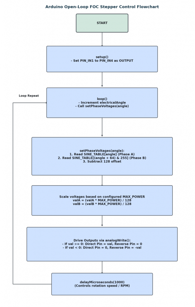
โปรแกรมนี้ทำหน้าที่ควบคุมสเต็ปเปอร์มอเตอร์ (Stepper Motor) แบบ Microstepping (Sine-Cosine Vector Control) เพื่อให้มอเตอร์หมุนได้อย่างราบรื่น นุ่มนวลและเงียบกว่าการสั่งเปิด-ปิดทีละสเต็ปแบบทั่วไป โดยสั่งงานผ่านไอซี H-Bridge L293D
1. ตารางคลื่นสัญญาณไซน์ (SINE_TABLE & PROGMEM)
- สร้างตารางค่า Sine Wave ความละเอียด 256 ตำแหน่ง นำไปเก็บไว้ในหน่วยความจำ Flash (PROGMEM) เพื่อประหยัดหน่วยความจำ RAM
- ค่าในตารางมีออฟเซ็ตอยู่ที่ 128 (ค่า 128 คือจุดศูนย์ / กระแสเป็น 0)
2. การคำนวณแรงดัน 2 เฟส (setPhaseVoltages)
- Phase A (ขดลวดชุดแรก) จะดึงค่า Sine ตามมุมกระแสไฟฟ้าปัจจุบัน (angle) แล้วลบออก 128 เพื่อให้ได้ค่าบวก/ลบ
- Phase B (ขดลวดชุดที่สอง) จะดึงค่า Cosine โดยนำมุมไปบวกเพิ่ม 64 (เทียบเท่าการเลื่อนเฟสไป 90° เพราะ 256/4 = 64)
- การจำกัดกำลัง ด้วยการนำค่าที่ได้ไปคูณกับ MAX_POWER เพื่อควบคุมไม่ให้มอเตอร์และไอซี L293D ร้อนเกินไป
3. การขับกระแสผ่าน H-Bridge (L293D)
- แยกการจ่ายสัญญาณ PWM (analogWrite) ตามเครื่องหมายของค่าที่คำนวณได้คือ
- ค่าเป็นบวก จะส่ง PWM เข้าขา + (เช่น IN1) และให้ขา – (IN2) เป็น 0
- ค่าเป็นลบ จะให้ขา + เป็น 0 และส่ง PWM (ค่าสัมบูรณ์) เข้าขา – เพื่อกลับทิศทางกระแส
4. การลูปหมุนมอเตอร์ (loop)
- ตัวแปร electricalAngle จะเพิ่มค่าขึ้นเรื่อยๆ ทีละ 1 ระดับ (เมื่อถึง 255 จะวนกลับมาเริ่มต้นที่ 0 ให้อัตโนมัติเนื่องจากเป็นชนิด uint8_t)
- การควบคุมความเร็วการหมุนด้วยคำสั่ง delayMicroseconds(1000) โดยหากลดเวลาลง มอเตอร์จะหมุนเร็วขึ้น และหากเพิ่มเวลา มอเตอร์จะหมุนช้าลง
การต่อวงจรสำหรับการทดลอง
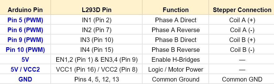
ไอซี L293D ทำหน้าที่ขับสเต็ปเปอร์มอเตอร์ที่มุมเฟสตามที่กำหนดจำนวน 2 เฟส (ขดลวด A และขดลวด B) โดยแต่ละเฟสจำเป็นต้องใช้ขา PWM จำนวน 2 ขาบนบอร์ด Arduino เพื่อควบคุมขั้วแรงดันไฟฟ้าทั้งด้านบวกและด้านลบ
การเพิ่มประสิทธิภาพการทำงาน
- ระบบป้องกันความร้อนสูงเกิน โดย L293D ใช้ทรานซิสเตอร์แบบ Bipolar Junction (BJT) และมีการระบายความร้อนออกมาค่อนข้างมาก แนะนำควรตั้งค่า MAX_POWER ให้อยู่ในช่วง 180–220 เพื่อป้องกันไม่ให้ระบบตัดการทำงานเนื่องจากความร้อนสูงเกินไป
- การควบคุมทิศทาง หากต้องการกลับทิศทางการหมุน ให้เปลี่ยนคำสั่ง electricalAngle++ เป็น electricalAngle – –
- การควบคุมความเร็ว ที่ฟังก์ชัน delayMicroseconds() จะเป็นตัวกำหนดความเร็วในการหมุน หากตั้งค่าความเร็วสูงเกินไป จะทำให้โรเตอร์อาจหยุดหมุนได้ (Stall) เนื่องจากระบบควบคุมแบบ Open-loop ไม่สามารถปรับชดเชยแรงบิดที่สูญเสียไปได้ในขณะทำงาน
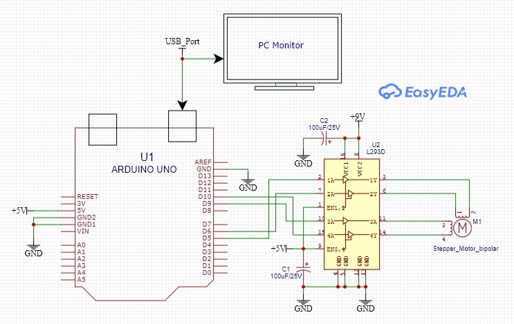
สำหรับในตอนที่ 1 ของบทความการควบคุมสเต็ปเปอร์มอเตอร์แบบ Bipolar Stepper Motor ด้วยวิธี Field-Oriented Control (FOC) โดยใช้บอร์ดประมวลผล Arduino UNO และไอซีขับกำลังเบอร์ L293D เป็นการแนะนำเนื้อหาเบื้องต้นเกี่ยวกับ หลักการทางคณิตศาสตร์ถึงรูปแบบการสร้างสัญญาณไซน์และโคไซน์ (Sine-Cosine Vector Control) สำหรับขับมอเตอร์, ตัวอย่างโค้ด Arduino ที่ใช้ในการทดลอง และการต่อวงจรระหว่างบอร์ด Arduino UNO ไอซี L293D กับสเต็ปเปอร์มอเตอร์ สำหรับใช้ในการทดลองในตอนต่อไปกันครับ.
Reference
- https://en.wikipedia.org/wiki/Field-oriented_control
- https://control.com/technical-articles/field-oriented-control-vector-control-for-brushless-dc-motors/
- https://www.analog.com/en/lp/001/field-oriented-control.html
- https://www.mathworks.com/discovery/field-oriented-control.html
- https://www.ti.com/lit/ds/symlink/l293d.pdf
- https://www.mantech.co.za/datasheets/products/L293X.pdf
- https://techweb.rohm.com/product/motor/motor-types/499/
- https://www.orientalmotor.com/stepper-motors/2-phase-stepper-motors-pkp-series.html
- https://community.simplefoc.com/t/driving-two-phase-bilpolar-steppers-with-three-phase-bldc-driver-hybrid-stepper-motor/5043
- https://simplefoc.com/
- https://gemini.google.com/
- https://www.pmdcorp.com/resources/type/articles/get/field-oriented-control-foc-a-deep-dive-article
